


At present, there are several connection modes of color LCD: MCU mode, RGB mode, SPI mode, VSYNC mode, MDDI mode, etc.
MCU mode: Currently the most commonly used connection mode, generally on 80 system (68 system no longer exists). Data bit transmission has 8 bits, 9 bits,16 bits and 18 bits. Connection is divided into CS/, RS(register selection), RD/, WR/, and then the data line. The advantages are simple and convenient control, no clock, and a synchronization signal. Disadvantages: need to consume GRAM, so difficult to be used on a bigger screen (above QVGA ).
RGB mode: The large-screen mode is used more frequently, and the data bit transmission can be divided into 6, 16, and 18 bits. Generally, the connection contains VSYNC or HSYNC, DOTCLK, VLD, ENABLE, and the rest is the data cable. Its pros and cons are the opposite of the MCU model.
SPI mode: it`s used less, connections are CS/, SLK, SDI, SDO four lines, less wired but more complex software control.
VSYNC Mode: This mode is under MCU mode, to add a VSYNC (frame synchronization) signal line for motion picture updates.
MDDI mode: Qualcomm proposed the Interface MDDI (Mobile Display Digital Interface) in 2004, by reducing the connection line, improving reliability, and reducing power consumption in mobile phones, which will replace SPI mode as a high-speed serial interface in the mobile space.
The connections contains host_data,host_strobe,client_data,client_strobe, power, and GND.
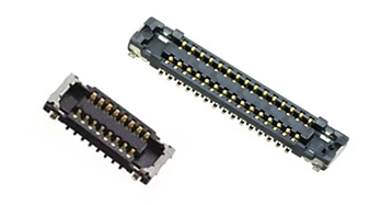
By checking the encapsulated interface diagram provided of the LCM module, developer can roughly see what interface it provides, mainly according to the user`s requirement to choose.
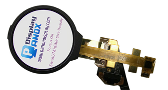
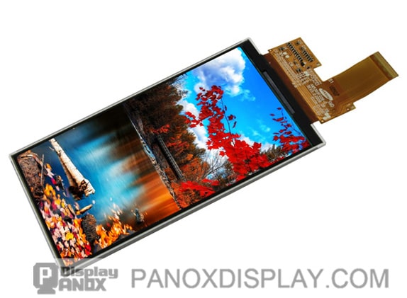
Related: Samsung 3.7 inch OLED, a standard RGB interface display, Model is AMS369FG06
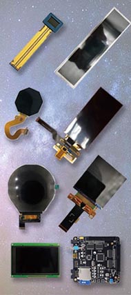
LCD has a variety of interfaces
Mainly according to LCD driving mode and control mode. It can be roughly divided into MCU interface and RGB interface.
The MCU interface can be divided into 8080 modes and 6800 modes, which is mainly the difference of timing.
RGB interface can be divided into analog RGB interface, ADC interface, and digital RGB interface.
As for the need for the HSNC, VSNC signal, this is in the RGB interface but also depends on what type of control-driven mode, it`s not necessary.
MCU interface: The command will be decoded and the timing generator will generate timing signals to drive COM and SEG drivers.
RGB interface: No difference with MPU when writing LCD register setting. The difference is only in how the image is written.
The signals required by MCU mode are WR, RD, RS, RESET, and CS.
RGB mode requires signals such as HSYNC, VSYNC, ENABLE, CS, and RESET, and some also require RS.
When using MCU mode, the data can be first stored in the IC internal GRAM and then written into the screen, so under this mode LCD can be directly connected to the MEMORY bus.
In RGB mode, it has no internal RAM. HSYNC, VSYNC, ENABLE, CS, RESET, and RS can be connected directly to MEMORY
Related: Samsung 2.6 inch OLED, a standard MCU interface display
The GPIO port is used to simulate waveform, but whether there are so many free GPIO ports is a problem to be considered. In addition, since it does not have RAM, the data is sent directly
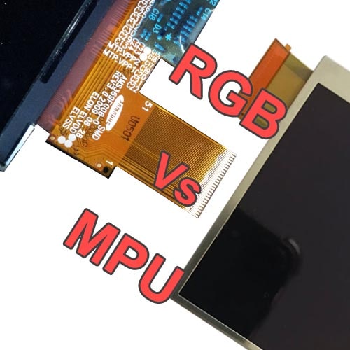
The main difference between MPU and RGB is:
MPU interface mode: Display data written to DDRAM, often used for still picture display.
RGB interface mode: Display data does not write to DDRAM, is directly written into the screen, is fast, and is often used to display video or animation.
Only TFT (Including OLED) displays have RGB interfaces.