


LCD stands for Liquid Crystal Display
TFT stands for Thin Film Transistor
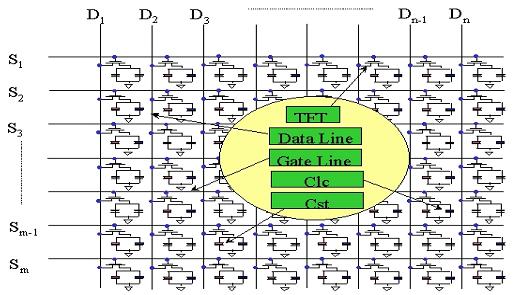
Currently most widely used active matrix LCD, also known as TFT-LCD. TFT-LCD stands for Thin-FilmTransistor Liquid-Crystal Display.
Active matrix:
Passive matrix LCD can be divided into TN-LCD (TwistedNematic-LCD), STN-LCD (SuperTN-LCD), and DSTN-LCD (Doublelayer STN-LCD). We are not going to go into detail here, but go to focus on TFT-LCD.
Passive matrix:
LCD has classification standards, according to the driving way can be divided into Passive Matrix and Active Matrix.
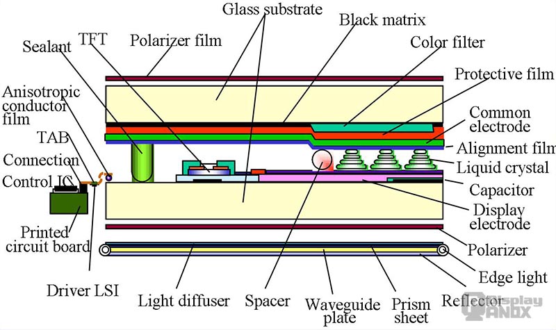
Now let's introduce the structure and display theory of TFT-LCD. To drive an LCD module, it`s necessary to have a systematic understanding of its structure.
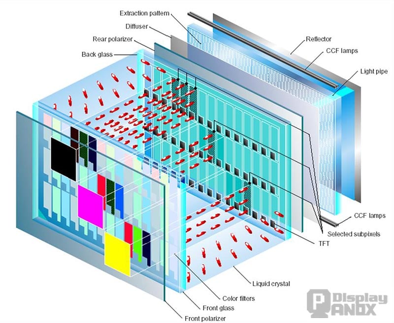
1. Structure of TFT-LCD

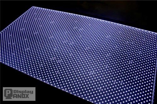
| Reflector CCF lamps Ligh pipe Extraction pattern Diffuser |
This part is mainly the light source part, CCFL or LED backlight source, other reflectors, and scatterers, to make light more evenly distributed |
| Rear polarizer Front Polarizer |
A polarizer turns natural light into a polarizing light |
| Selected Subpixels TFT Liquid crystal Color filters |
This part is the core part of the LCD, the selection of light source conduction, blocking, color control in this part. |
| Back glass Front glass |
Protect layers |
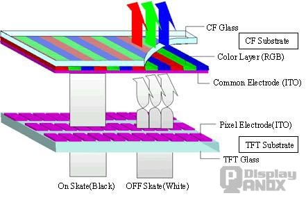
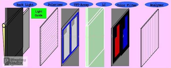
1.1 TFT-LCD Structure Function
(1) Backlight Plate Module: Provides the source of light;
(2) Above and Below Polarizing Plate, TFT Glass Substrate, Liquid Crystal: Forming polarized light, controlling the passage of light;
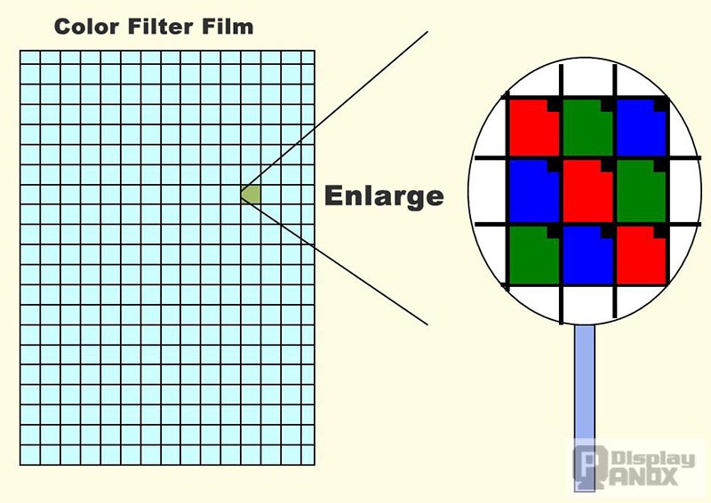
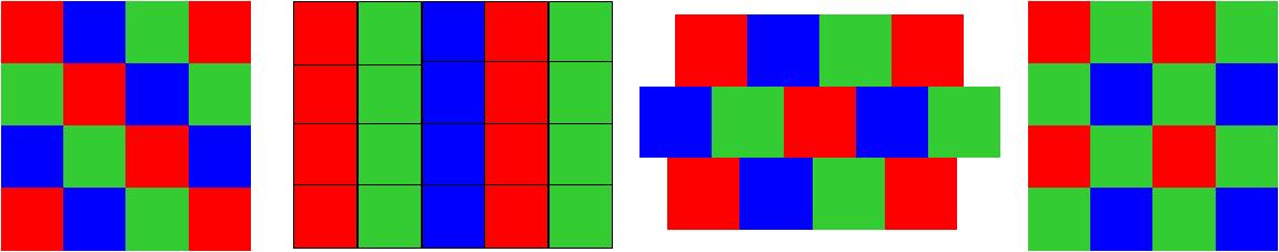
(3) Color Filter: Provide TFT LCD red, green, and blue (the three primary colors of light) source;
(4) ITO Transparent Conductive Layer: Provides a transparent conductive path;
(5) Photo Spacer: Provide a fixed height for color filters and TFT Glass Substrate. As a space for filling the liquid crystal. And as the above and below Glass support.
1.2 TFT-LCD Side view of the structure
2. TFT-LCD Display Principle
2.1 Backlight of liquid crystal
Backlight is the light source of the display. There are two common types of LCD backlight: CCFL backlight and LED backlight
CCFL
Cold Cathode Fluorescent Lamp, CCFL in short, characterized by high power, high brightness, and low energy consumption, is widely used in monitor, lighting, and other fields.
LED Backlight
Compared with CCFL, LED has the advantages of low power consumption, uniform light source, long life, and small size, the price will be a little more expensive, but now the most of tablet display used TFT-lCD seems to be LED backlight.
LED and LED backlight
The so-called “LED display” on the market is actually an "LED backlight liquid crystal display" Now popular LCD monitor belongs to the "CCFL backlight LCD". So the two are still liquid crystal displays, but the backlight is different.
The so-called “LED display” on the market is actually an "LED backlight liquid crystal display" Now popular LCD monitor belongs to the "CCFL backlight LCD". So the two are still liquid crystal displays, but the backlight is different.
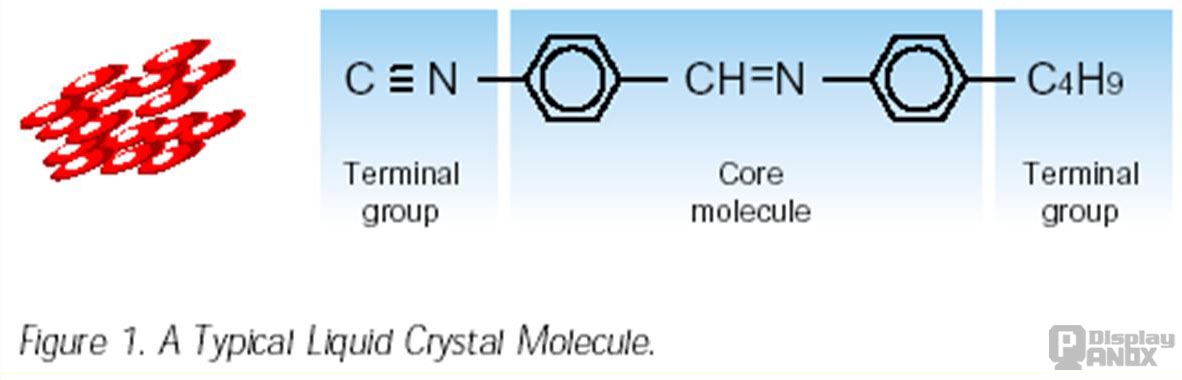
2.2 Liquid Crystal Introduction
2.2.1 The shape of liquid crystal
TFT-LCD uses TN (Twist Nematic) liquid crystal with elliptical molecules.
2.2.2 The characteristics of liquid crystal
TN liquid crystals are usually connected in series along the direction of the long axis, and the long axes are arranged parallel to each other. When crystal molecules touched the socket, they are arranged in the direction of the tank.
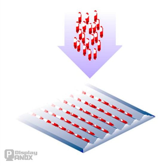
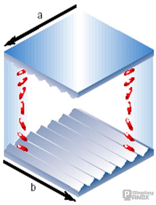
2.2.3 Liquid crystal vertical distribution
When the liquid crystal is contained in the middle of two grooves, and the grooves are perpendicular to each other, the arrangement of liquid crystal molecules is:
Upper surface molecules: along the direction A.
Lower surface molecules: along the direction B.
Molecules between the above and below surfaces will cause the effect of rotation. So liquid crystal molecules rotate 90 degrees between the two grooves.
2.2.4 Light and liquid crystal molecules cause a deflection effect
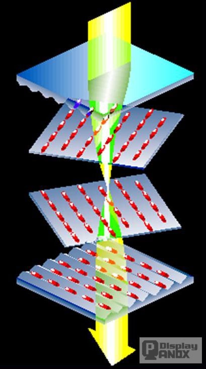
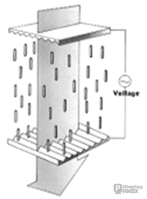
2.2.5 The Liquid Crystal Is Evenly Spread Under The Voltage
When a voltage is applied between the above and below surfaces, liquid crystal molecules line up in the direction of the electric field, forming an upright alignment. At this time, the incident light is not affected by liquid crystal molecules, straight out of the above surface.
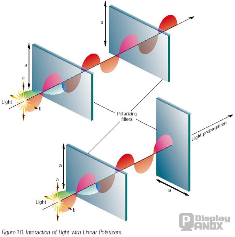
2.2.6 Characteristics Of Polarizing Plate
Functions: Filters the unpolarized light (common light) into a polarization of light. When the unpolarized light passes through a polarized plate in the direction, the light is filtered into a linear biased aurora parallel to the A direction.
Above image: The linear polarization of light continues as light passes through the second polarizing plate.
Below image: Passing through the second patch, the light is completely blocked.
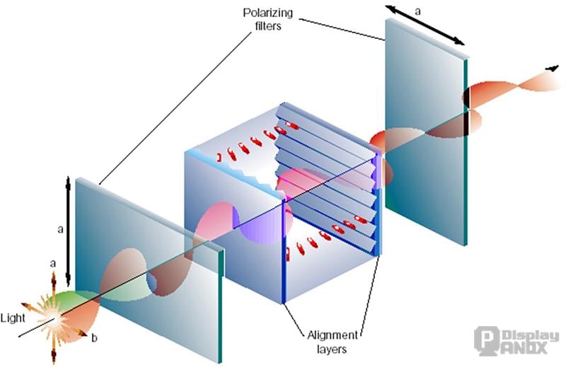
The optical effect generated by the combination of the polarizer, trough surface, and liquid crystal is shown in the figure below
When the above and below polarizers are perpendicular to each other, if no voltage is applied, the light can pass through
When a voltage is applied, the light is completely blocked
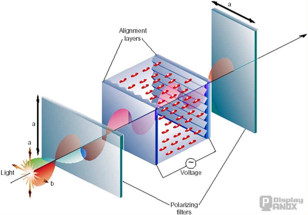
When an electric current passes through the transistor, the electric field changes, causing the liquid crystal molecules to deflect, so as to change the polarity of the light, and then use the polarizer to control the light and dark state of the Pixel. This allows you to control the brightness of the light, and if you want to display color, we'll talk about color filters later.