



Capacitive touch screens have become standard in smartphones, tablets, and many other electronic devices. Yet two displays with similar specifications can behave quite differently depending on how their touch sensors are integrated.
When selecting a touch display module, one common question is whether the screen uses In-Cell, On-Cell, or OGS technology. These terms describe the position of the touch-sensing electrodes within the display assembly. That position affects the module's thickness, manufacturing cost, electrical interference, mechanical design, and long-term reliability.
In-Cell offers a high level of integration, On-Cell places the touch sensor directly on the display panel, and OGS combines the touch sensor with the cover glass. Each approach has its advantages, but none is suitable for every application.
Understanding these structures is particularly important when choosing displays for consumer electronics, industrial equipment, and automotive systems, where cost and operating conditions often matter as much as thickness.
From Resistive to Capacitive Touch Screens
Before capacitive touch became widely used in consumer electronics, resistive touch screens were common in handheld terminals, navigation devices, and industrial control systems.
A conventional resistive touch panel contains two conductive layers separated by a small air gap and insulating spacers. When pressure is applied, the layers make contact. The controller measures the resulting voltage changes to determine the touch coordinates.
This structure works with fingers, ordinary styluses, and most gloves because it relies on mechanical pressure rather than the electrical properties of the object touching the screen.
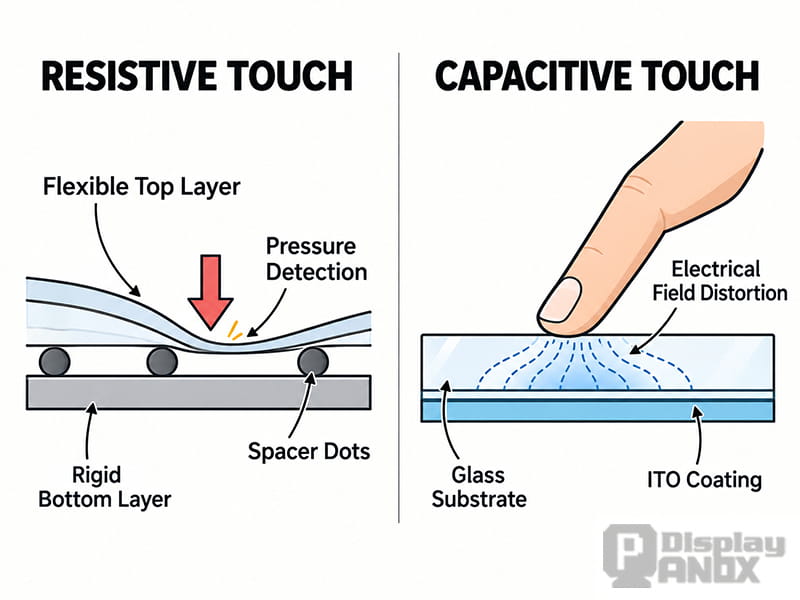
Resistive touchscreens detect physical pressure between conductive layers, while capacitive touchscreens detect changes in capacitance.
However, resistive panels require physical pressure to activate. Their multiple conductive layers can also reduce optical transmission, while the flexible top surface is subject to wear. Conventional resistive technology generally offers a less responsive experience than modern multi-touch capacitive systems.
Resistive touch has consequently become less common in consumer electronics, although it remains useful in selected industrial, medical, and specialized equipment where pressure-based input is preferred.
Capacitive touch operates differently.
A capacitive touch screen detects changes in capacitance when a finger or another suitable conductive object interacts with an electric field near the sensor electrodes. A light touch is normally enough to register an input.
Most modern capacitive displays use projected capacitive technology (PCAP), which supports accurate positioning and multi-touch gestures.
The trade-off is that capacitive sensing can be affected by electrical noise, water, condensation, and insulating gloves. These problems can often be reduced through suitable touch-controller design and firmware tuning, but they must be considered during product development.
For a more detailed explanation of the sensing principle, see Capacitive Touch Screen: How It Works, Types, and Applications.
What Is the Difference Between In-Cell, On-Cell, and OGS?
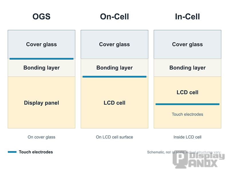
Comparison of conventional external touch, OGS, On-Cell, and In-Cell display structures.
The main difference between In-Cell, On-Cell, and OGS touch screens is where the touch sensor sits in relation to the display panel and cover glass.
A projected capacitive sensor typically uses patterned transmitting and receiving electrodes arranged in an X-Y sensing matrix. These electrodes are often made from indium tin oxide (ITO), a transparent conductive material, although other conductive materials can also be used.
In a conventional external touch panel, the sensor is manufactured separately and laminated onto the display assembly.
In integrated touch structures, the electrodes are moved closer to or inside existing display components. This reduces the need for additional sensor substrates and bonding layers.
The three common approaches are OGS, On-Cell, and In-Cell.
OGS Touch Screen: Integrating the Sensor into the Cover Glass
OGS stands for One Glass Solution. It is also commonly associated with Sensor-on-Lens technology.
In an OGS touch screen, the capacitive sensing electrodes are patterned directly onto the inner surface of the cover glass. The same piece of glass provides both surface protection and touch sensing.
Traditional glass-glass (G+G) capacitive touch panels generally use a separate sensor glass bonded to the protective cover glass. OGS removes that additional sensor substrate, reducing the thickness and weight of the touch assembly.
With fewer material layers, OGS can also reduce optical interfaces and improve light transmission compared with a conventional G+G construction.
The technology gained considerable attention during the development of thinner smartphones and tablets, particularly when manufacturers were trying to reduce the thickness of the front display assembly.
However, integrating the sensor into the protective glass creates a mechanical limitation.
If the cover glass breaks and the fracture damages the conductive electrode pattern or its connections, the touch function may fail. Even when touch operation remains possible after a crack, repairing the assembly can be more complicated because the protective glass and sensing structure are integrated.
Cover glass manufacturing also becomes more demanding.
Irregular outlines, holes, narrow borders, and complex edge treatments can increase processing difficulty and reduce manufacturing yield. Cutting and strengthening processes must be carefully controlled to avoid damaging the glass or affecting the electrode pattern.
For products requiring frequent cover-lens customization or high mechanical durability, these manufacturing and repair considerations can outweigh the thickness advantage.
OGS remains a useful solution when a thin touch assembly is required and the cover-glass design is suitable for the manufacturing process.
On-Cell Touch Screen: Placing the Sensor on the Display Panel
On-Cell technology integrates the capacitive touch sensor onto the outer surface of the display cell instead of using a separate touch sensor substrate.
In a typical TFT LCD structure, the touch electrodes are formed on the outer surface of the color-filter (CF) glass, generally beneath the upper polarizer.
This arrangement removes the need for a separate sensor glass and its associated bonding structure, helping reduce the overall module thickness.
The basic display cell remains largely separate from the touch-sensing electrodes, which can simplify certain aspects of manufacturing compared with embedding the electrodes inside the display cell.
However, the touch sensor sits close to the display-driving circuitry.
Switching signals generated during image refresh can couple into the touch electrodes and interfere with capacitance measurements. The sensor pattern, grounding, controller, and signal-processing algorithms must therefore be designed to maintain a stable signal-to-noise ratio.
On-Cell structures are not limited to TFT LCDs.
In OLED and AMOLED displays, touch electrodes can be formed above the display's encapsulation layer. This approach is widely used in modern OLED designs, particularly flexible AMOLED panels, where reducing additional substrates helps preserve a thin and lightweight structure.
The manufacturing process differs from LCD On-Cell integration because OLED panels do not use the same liquid-crystal and color-filter glass arrangement as conventional TFT LCDs.
More information about this structure is available in Why On-Cell Touch Is Mainstream in OLED Displays.
On-Cell offers a practical balance between integration, manufacturing complexity, and touch performance. Its final cost and suitability depend on the display technology, panel design, production volume, and available supply chain.
In-Cell Touch Screen: Integrating Touch into the Display Cell
In-Cell technology takes integration further by incorporating the touch-sensing function into the display cell itself.
In an In-Cell TFT LCD, sensing electrodes may be built into existing display layers or share electrodes already used for display operation.
Some designs reuse the common electrode, known as VCOM, for capacitive touch sensing. Other designs incorporate dedicated electrodes into the internal display structure.
This reduces the need for separate touch sensor materials and allows manufacturers to create thin, highly integrated display modules.
In high-volume consumer electronics, removing external sensor components can also reduce material, assembly, and interconnection costs.
However, In-Cell integration introduces more complicated electrical and manufacturing requirements.
Because the touch-sensing circuitry is closely integrated with the pixel-driving system, display operation and touch detection can interfere with one another.
In architectures that share electrodes between display driving and touch sensing, the controller must coordinate these two functions carefully.
A common approach is time-division driving, in which the display and touch functions operate during different time intervals. Touch sensing can take place when the relevant display-driving activity is temporarily paused or reduced.
This arrangement helps prevent display switching noise from overwhelming the comparatively small capacitance changes being measured.
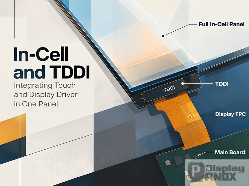
Many In-Cell LCD systems use Touch and Display Driver Integration (TDDI), which coordinates the touch controller and display driver, often within a single integrated circuit.
TDDI can reduce component count, simplify connections, and improve coordination between display refresh and touch scanning.
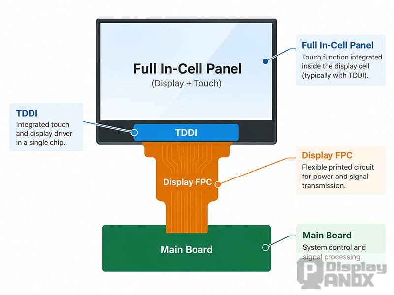
Full In-Cell display architecture with integrated touch and display driver IC (TDDI).
The technical challenge is that the display and touch functions are now more closely dependent on each other. Electrode resistance, parasitic capacitance, timing, electrical noise, and controller firmware all influence touch performance.
An In-Cell panel may therefore be thinner and less expensive to assemble at scale, while requiring more complicated panel manufacturing and signal optimization.
As In-Cell and TDDI technologies have matured, their use has expanded beyond smartphones into other applications, including selected industrial and automotive displays.
For further technical details, see What Is an In-Cell Display? A Practical Guide to Integrated Touch Technology.
In-Cell vs On-Cell vs OGS: Key Differences
The following comparison summarizes how touch integration affects display construction and engineering requirements.
|
Feature |
OGS |
On-Cell |
In-Cell |
|---|---|---|---|
|
Touch sensor location |
Inner surface of the cover glass |
Outer surface of the display cell |
Inside the display cell |
|
Integration approach |
Cover glass and touch sensor combined |
Touch sensor integrated onto the display panel |
Touch function incorporated into the display structure |
|
Module thickness |
Thin compared with conventional G+G touch |
Thin, with no separate sensor glass |
Potentially the thinnest integrated structure |
|
Manufacturing challenge |
Cover-glass processing and sensor patterning |
Sensor integration and noise control |
Complex display manufacturing and touch/display coordination |
|
Cost considerations |
Sensitive to cover-glass complexity and yield |
Depends on panel technology and production volume |
Potential system cost advantage at high volume |
|
Mechanical considerations |
Cover-glass damage may affect touch operation |
Separate protective cover can be used |
Separate protective cover can be used |
|
Typical applications |
Thin touch assemblies and selected customized devices |
LCD and AMOLED products, including flexible OLED |
Smartphones, compact devices, and selected industrial or automotive displays |
These differences describe typical structures rather than fixed performance rankings.
For example, In-Cell often provides the greatest integration advantage, but the finished module is not automatically thinner than every On-Cell product. Cover glass, polarizers, adhesives, mechanical support, and other components still contribute to total thickness.
Similarly, no single architecture guarantees better touch sensitivity or mechanical durability. The complete display assembly and its operating conditions determine the final result.
Why Touch Noise and Signal Interference Matter
The closer the touch electrodes are to the display-driving circuitry, the more carefully electrical interference must be managed.
A capacitive touch controller measures relatively small changes in electrical capacitance. During display refresh, TFT switching, common-electrode signals, and other high-frequency electrical activity can introduce unwanted signals into the sensing system.
If the interference is too strong, the controller may struggle to distinguish a real touch from background noise.
The results can include inaccurate coordinates, missed touches, unstable tracking, or false touch events.
In an In-Cell display, this interaction can be particularly challenging because the sensing electrodes may share part of the display's electrical structure.
On-Cell displays can also experience coupling noise, especially when the touch electrodes are located close to the active display layers.
Touch performance therefore depends on more than the physical electrode position. Controller sensitivity, filtering, grounding, electrode resistance, and scan timing are equally important.
During development, engineers may need to compare display-refresh signals with touch-scanning activity using oscilloscopes and other diagnostic equipment.
Optimizing these signals can require repeated adjustments to timing, firmware settings, driving frequency, and noise-filtering parameters.
A display that works correctly under one operating condition may behave differently when the screen brightness, refresh rate, power supply, or surrounding electrical environment changes.
This is one reason why integrated touch displays should be evaluated as complete systems rather than as isolated display panels.
Wet Fingers, Gloves, and Humidity
Wet-finger operation and glove compatibility are common concerns in industrial and automotive touch screens.
Water droplets and condensation can modify the electric field around capacitive electrodes. Under certain conditions, the controller may interpret these changes as touch input or have difficulty tracking a real finger.
Gloves introduce a different problem. Their insulating material increases the effective distance between the finger and the sensing electrodes, weakening the capacitive signal.
Increasing sensitivity may help detect gloved input, but excessive sensitivity can also make the system more vulnerable to noise and unintended activation.
Modern capacitive controllers can use water rejection, adaptive sensing, and signal-processing techniques to improve performance.
These challenges are not exclusive to In-Cell technology. OGS, On-Cell, and external capacitive touch panels can all be affected by water, gloves, and electrical interference.
The difference lies in how the sensor structure and controller respond to those conditions.
For applications involving wet operation or gloves, actual performance should be verified using the intended cover-glass thickness, glove material, and environmental conditions.
How to Choose Between In-Cell, On-Cell, and OGS Touch Screens
Selecting the right touch structure involves balancing five main considerations: thickness, integration, noise immunity, reliability, and cost.
The relative importance of each factor changes with the application.
Consumer Electronics: Thickness and Production Cost
Smartphones, tablets, and other high-volume consumer devices place considerable value on thin construction and efficient component integration.
In-Cell technology is attractive for these applications because it can eliminate separate touch sensor layers and reduce the number of interconnections.
When combined with mature TDDI solutions, In-Cell can provide a favorable system-level cost structure, especially in large production volumes.
On-Cell remains another practical option, particularly for AMOLED and flexible OLED products where touch integration above the display structure is already well established.
For cost-sensitive consumer products, the best choice depends on available panel designs and the total module price rather than the technology name alone.
A mature On-Cell module may be more economical than developing or sourcing a specialized In-Cell panel for a particular project.
Industrial Equipment: Durability and Customization
Industrial displays often face requirements that differ from those of consumer electronics.
A factory control panel may need to operate with gloves, tolerate moisture, resist mechanical impact, or use thick protective glass.
In these situations, minimizing thickness is usually less important than maintaining reliable touch operation.
Many industrial products therefore continue to use external projected capacitive touch panels, including G+G and glass-film constructions.
A separate touch sensor can offer more flexibility when adjusting cover-glass thickness, sensor layout, mounting structure, or controller selection.
It may also be easier to customize the touch assembly without modifying the underlying LCD panel.
Where gloves or pressure-based input are essential, resistive touch remains a possible alternative.
In-Cell and On-Cell displays can still be used in industrial equipment, provided their electrical and mechanical characteristics meet the application requirements.
The final selection should account for the complete product design, including the enclosure, power supply, operating environment, and expected service life.
Automotive Displays: Reliability Comes First
Automotive touch screens face demanding environmental and electrical conditions.
Depending on the installation location, a display may experience high temperatures, cold starts, vibration, sunlight exposure, electromagnetic interference, and repeated touch operation over a long service life.
These conditions make touch stability a major consideration.
In-Cell technology can create additional engineering challenges because touch sensing is closely coupled with display operation. Temperature-dependent electrical characteristics, display-driving noise, and electromagnetic interference must be controlled across the required operating range.
However, high-temperature touch drift is not an unavoidable characteristic of every In-Cell display.
Well-designed In-Cell automotive systems can meet demanding reliability requirements through appropriate electrode design, driving methods, controller algorithms, and environmental validation.
On-Cell and external capacitive touch solutions are also used in automotive applications. Their relatively flexible sensor and cover-glass configurations can be useful when thick protective surfaces, special mounting requirements, or customized touch characteristics are needed.
For automotive projects, the decision should be based on verified performance under the specified environmental conditions rather than assuming one integration method is inherently more reliable.
Why the Lowest-Cost Touch Panel Is Not Always the Lowest-Cost Solution
Touchscreen cost cannot be evaluated solely by counting the number of glass layers.
OGS removes a separate sensor substrate, but complicated cover-glass shapes, holes, or special processing requirements can increase manufacturing costs.
On-Cell eliminates a separate sensor glass and may simplify the module stack, although production yield and panel availability still influence pricing.
In-Cell can reduce component and assembly costs through integration, particularly when mature designs are manufactured in large quantities. On the other hand, specialized In-Cell panel development may involve higher engineering costs and more demanding production processes.
External capacitive touch panels add components and bonding steps, but their established manufacturing processes and customization flexibility may offer better economics for lower-volume industrial projects.
Production yield, tooling investment, minimum order quantities, assembly complexity, and replacement costs all contribute to the final cost.
The most economical solution is therefore the one that meets the required performance and reliability targets at an acceptable total cost.
Touchscreen Selection and Customization with Panox Display
At Panox Display, touch integration is considered alongside display specifications such as screen size, resolution, brightness, interface, and operating temperature.
For applications requiring a compact and lightweight module, integrated In-Cell or On-Cell displays may offer clear advantages.
For industrial and automotive projects with specialized cover-glass requirements, an external capacitive touch panel may provide greater design flexibility.
Panox Display supports different touch panel configurations, including capacitive touch panels (CTP), resistive touch panels (RTP), G+G, G+F, G+F+F, and OGS structures.
Touch panel selection can also involve cover-glass dimensions, thickness, surface treatment, optical bonding, touch-controller compatibility, FPC design, and environmental requirements.
These details should be confirmed early in product development to avoid unnecessary mechanical changes or touch performance problems during final assembly.
More information is available through Panox Display Custom Touch Panel Solutions.
Conclusion: The Best Touchscreen Structure Depends on the Application
In-Cell, On-Cell, and OGS technologies all aim to integrate capacitive touch more efficiently, but they achieve that goal in different ways.
OGS combines the sensing electrodes with the cover glass, reducing the number of glass substrates while making touch performance more closely dependent on the protective surface.
On-Cell places the touch sensor on the display panel, offering a thin structure without the full complexity of embedding the sensing function inside the display cell.
In-Cell provides deeper integration and can reduce overall module thickness and system cost, particularly in high-volume products. Its electrical and manufacturing requirements are also more demanding.
For consumer electronics, thickness, integration, and cost often guide the decision. For industrial and automotive products, environmental performance, mechanical durability, and long-term reliability may carry greater weight.
There is no universal ranking that makes In-Cell, On-Cell, or OGS the best choice in every situation.
The right solution comes from balancing cost and performance around the actual requirements of the finished product.