



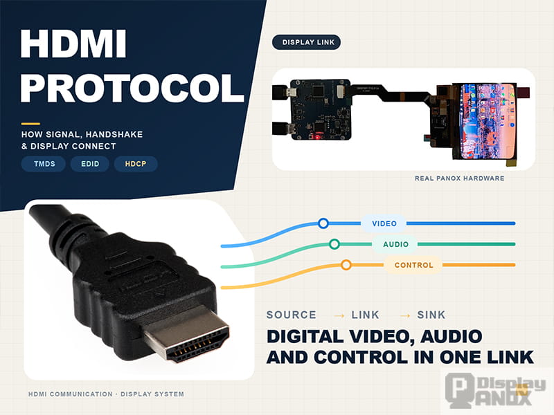
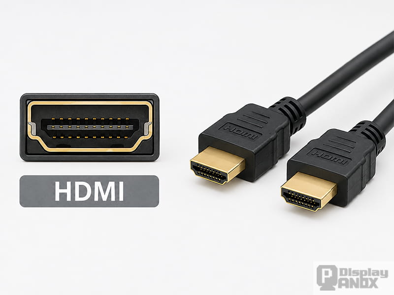
HDMI is easy to recognize as a connector, yet the connector is only the visible part of a much larger communication system. Before an image reaches a display, the source and receiving device must detect each other, exchange capability information, select a compatible format, establish any required content protection, and start a high-speed data link.
This coordinated process is commonly called the HDMI protocol. It covers far more than video transmission. HDMI also carries digital audio, timing information, device capabilities, control commands, content-protection data and, in some systems, return audio.
The current HDMI 2.2 specification expands the available bandwidth to as much as 96 Gbps and continues the transition toward Fixed Rate Link transmission for demanding video formats. At the same time, support for classic TMDS remains important because billions of existing HDMI products still depend on it.
What Is the HDMI Protocol?
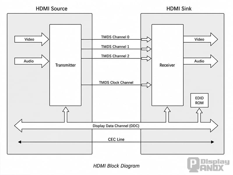
The HDMI protocol is a collection of electrical signaling rules, data formats and control procedures used to connect an audiovisual source to a receiving device.
A basic HDMI system contains three possible device roles:
| Device role | Function | Typical examples |
|---|---|---|
| Source | Generates the HDMI output | Computer, graphics card, camera, game console or media player |
| Sink | Receives and displays or processes the HDMI signal | Monitor, television, projector or HDMI receiver board |
| Repeater | Receives one HDMI signal and retransmits it | AV receiver, splitter, switch, extender or signal processor |
A product may contain more than one role. An AV receiver, for example, behaves as a sink at its HDMI inputs and as a source at its HDMI output.
The high-speed media link is only one part of this architecture. Other channels handle hot-plug detection, display identification, device control and content protection. This explains why a cable can be electrically connected while the screen still reports “No Signal.”
What Happens When an HDMI Cable Is Connected?
An HDMI connection normally develops through several stages.
-
The source provides the HDMI 5 V supply. This voltage supports connection detection and related interface functions.
-
The receiving device asserts Hot Plug Detect. HPD informs the source that a sink is connected and ready for communication.
-
The source reads the display’s EDID. This exchange takes place through the Display Data Channel, an I²C-based communication path.
-
A compatible video and audio mode is selected. The source compares its output capabilities with the resolutions, refresh rates, color formats and audio modes described by the sink.
-
Content protection is authenticated when required. Protected commercial media may require an HDCP session before playback starts.
-
The high-speed video link begins. The signal is carried through TMDS or FRL, depending on the supported HDMI mode and the negotiated link configuration.
EDID is fundamental to plug-and-play display operation. VESA describes EDID as the established display-identification mechanism used across HDMI, DisplayPort and other display interfaces.
A failure at any stage may interrupt the connection. Incorrect HPD timing can prevent detection, corrupted EDID can cause the source to select the wrong format, and an HDCP mismatch can block protected content even when ordinary desktop video works correctly.
How TMDS Carries HDMI Video and Audio
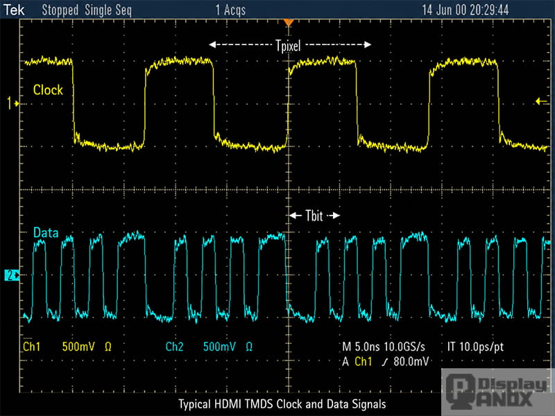
Traditional HDMI transmission uses TMDS, short for Transition-Minimized Differential Signaling.
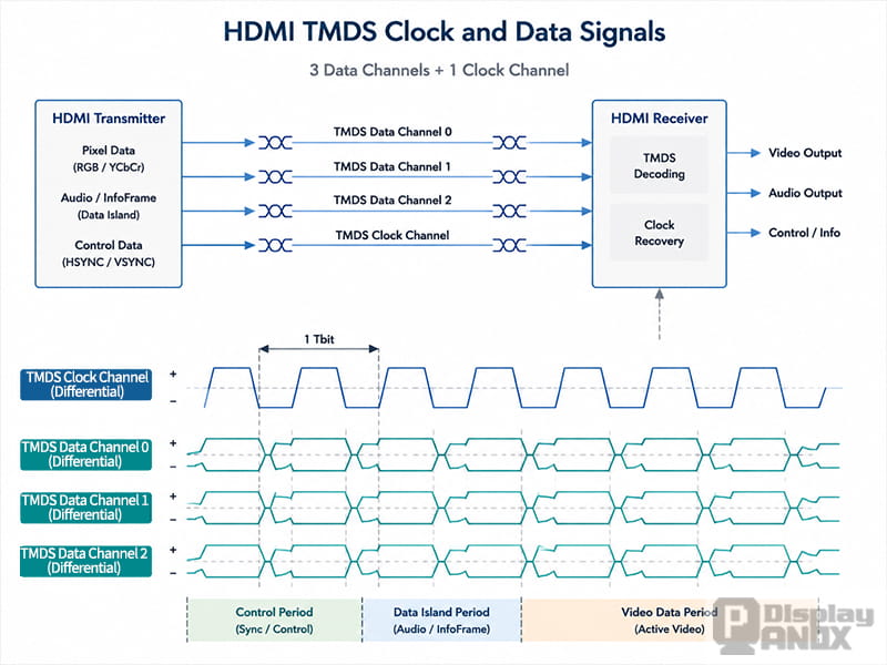
A classic TMDS link contains three high-speed data channels and one separate clock channel. The differential structure improves noise immunity, while the encoding method reduces unnecessary electrical transitions and helps control electromagnetic interference. Texas Instruments describes HDMI TMDS transport as four differential pairs: three data pairs and one clock pair.
TMDS should not be treated as another name for HDMI. It is the principal high-speed signaling method used by classic HDMI modes.
During active video, each of the three channels receives an 8-bit component value and converts it into a 10-bit transmitted character. Depending on the selected color format, the three channels may represent RGB or YCbCr components.
Classic HDMI divides the stream into three main periods:
| Transmission period | Main purpose |
|---|---|
| Video Data Period | Carries active image pixels |
| Data Island Period | Carries audio packets, InfoFrames and auxiliary data |
| Control Period | Carries synchronization and control information between active periods |
Audio does not require a separate analog wire or an independent high-speed lane. It is packetized and inserted into Data Island periods, generally during the blanking portions of the video timing. Guard bands and preambles help the receiver distinguish between control, video and packetized data.
This three-period structure and the sharing of the TMDS channels between video, audio and control information are also illustrated in the supplied HDMI technical material.
Why TMDS Uses 8-Bit-to-10-Bit Encoding
Directly transmitting raw parallel pixel values would produce patterns with poor DC balance and a large number of signal transitions. Both conditions make high-speed transmission more difficult.
TMDS encoding evaluates each incoming 8-bit video value and produces a 10-bit output character. The coding process is designed to reduce transitions and maintain long-term electrical balance across the channel. The result is a signal that is more suitable for differential transmission over an HDMI cable.
For HDMI modes based on TMDS, the clock pair remains a dedicated clock channel. The receiver uses that clock to recover the data carried on the three accompanying channels.
Classic HDMI physical-layer validation therefore pays close attention to clock and data relationships. Eye opening, clock jitter, duty cycle, rise and fall time, overshoot, undershoot, inter-pair skew and intra-pair skew are among the measurements discussed in the supplied Tektronix source-testing paper.
TMDS vs FRL: What Changed in Modern HDMI?
Higher resolutions, deeper color and faster refresh rates eventually required a different link architecture. HDMI 2.1 introduced FRL, or Fixed Rate Link, and HDMI 2.2 extends the available FRL bandwidth further.
FRL and TMDS can exist in the same HDMI receiver or transmitter. The selected path depends on the capabilities declared by the connected devices. AMD’s HDMI subsystem documentation, for example, describes separate TMDS and FRL processing paths selected according to source and sink capability.
| Feature | TMDS | FRL |
|---|---|---|
| Main use | Classic HDMI transmission | Higher-bandwidth HDMI modes |
| Lane arrangement | Three data lanes plus a dedicated clock lane | Three or four high-speed data lanes |
| Clocking | Separate forwarded TMDS clock | Clock recovered from the data stream |
| Link setup | Starts with the selected TMDS clock rate | Performs link training before normal transmission |
| Data protection | TMDS encoding | Packetization, 16b/18b encoding and forward error correction |
| Typical role | Broad compatibility and established resolutions | High refresh rate, high color depth and larger resolutions |
With FRL, the pair previously used as the TMDS clock can become an additional data lane. HDMI 2.1 implementations commonly support three- or four-lane FRL configurations at several defined lane rates.
FRL also introduces link training. During training, the source and sink evaluate the connection and select a link rate that the complete signal path can support. Forward error correction provides additional protection against transmission errors.
The current HDMI 2.2 specification raises maximum bandwidth to 96 Gbps and supports formats including uncompressed 4K at 240 Hz and 8K at 60 Hz with full chroma and higher color depths. HDMI 2.2 still requires TMDS support for backward compatibility.
The Supporting Channels Inside an HDMI Connection
DDC and EDID
The Display Data Channel is a low-speed communication path based on I²C. Its best-known function is allowing the source to read EDID from the sink.
EDID may contain the preferred resolution, supported timings, refresh rates, color formats, audio capabilities and other display information. In an HDMI controller board, EDID may be stored in an EEPROM, integrated memory or firmware-controlled memory.
A wrong EDID does not necessarily stop all output. Some sources fall back to a safe resolution, while others select a mode that the controller or panel cannot display. This can lead to a low-resolution image, incorrect refresh rate, missing audio or a completely blank screen.
HPD
Hot Plug Detect reports the connection state of the sink. It also gives the sink a way to request that the source repeat part of the connection process.
HPD is not part of the image data. A valid TMDS or FRL design still needs correct HPD voltage levels and timing. HDMI devices and redrivers often include dedicated HPD level-shifting circuitry because the system logic may operate at a lower voltage than the external HDMI signal.
HDCP
HDCP, or High-bandwidth Digital Content Protection, protects licensed audiovisual content while it travels between compatible devices.
The source and sink authenticate each other and establish shared values used to protect the transmitted content. If authentication fails, protected video may be blocked even though menus, desktop images or unprotected test patterns appear normally.
HDCP is related to HDMI operation, but it is not the high-speed video transport itself. TMDS or FRL carries the media stream; HDCP controls how protected content within that stream is authenticated and encrypted.
CEC
Consumer Electronics Control is a low-speed, single-wire communication bus. It allows compatible AV products to discover and control one another.
CEC functions may include one-touch playback, automatic input switching, shared standby control and operation of several connected products through one remote control. NXP describes CEC as a bus that allows AV products to discover and communicate with each other across an HDMI system.
CEC does not carry video or audio. A CEC problem may affect automatic control while leaving the displayed image unchanged.
ARC and eARC
Audio Return Channel allows a display to send audio back through the HDMI connection to an AV receiver or sound system.
eARC expands this function with support for more advanced audio formats and higher audio quality. HDMI 2.2 continues to include eARC among its major audio and connectivity features.
Why a Bare LCD or OLED Panel Cannot Usually Accept HDMI Directly
Most bare LCD and OLED panels do not include an HDMI receiver. Their native interfaces are designed for short internal connections to a processor or bridge IC.
Common panel interfaces include:
These interfaces use different voltage levels, clocks, lane arrangements, packet formats and initialization sequences. An HDMI cable does not translate HDMI into MIPI, LVDS or eDP by itself.
An HDMI controller board performs that conversion. The board receives and decodes the HDMI stream, reads or provides EDID, processes the selected input timing, scales the image when necessary, and generates the output format required by the panel. It may also handle panel power sequencing, backlight control, touch communication, audio output and on-screen controls.
Panox Display develops HDMI controller and driver board solutions for selected LCD and OLED panels, including HDMI-to-MIPI, HDMI-to-RGB, HDMI-to-LVDS and HDMI-to-eDP configurations. Firmware and cable sets are matched to the panel rather than selected only by connector type.
Why Resolution Alone Does Not Define HDMI Compatibility
A label such as “1080p,” “4K” or “8K” does not provide enough information to determine whether a display system will work.
Required bandwidth also depends on:
-
Refresh rate
-
Color depth
-
RGB or YCbCr format
-
Chroma sampling
-
Blanking intervals
-
HDR format
-
Compression
-
Audio configuration
For example, 3840 × 2160 at 30 Hz requires considerably less link bandwidth than the same resolution at 120 Hz. A 10-bit 4:4:4 signal also carries more data than an 8-bit 4:2:0 signal.
The receiving HDMI IC may support a high input bandwidth while the scaler, bridge or panel interface cannot produce an equivalent output. Compatibility must therefore be checked across the entire path:
HDMI source → cable → HDMI receiver → video processor → panel interface → display panel
A controller advertised as “4K compatible” may accept only specific combinations of frame rate, color depth and chroma. The complete input and output timing table should be reviewed before the board is matched to a panel.
HDMI Version Numbers Do Not Describe Every Feature
HDMI version labels are useful, but they do not replace a detailed feature list.
HDMI Licensing Administrator has explained that HDMI 2.1 features are optional and that products promoted as HDMI 2.1 should identify the features they actually support. A product may therefore support an 18 Gbps TMDS mode without supporting FRL, 48 Gbps, VRR or every other feature associated with the specification.
The same practical rule applies during display-system selection: confirm the required bandwidth, refresh rate, FRL or TMDS mode, HDR format, HDCP version, audio capability and gaming features individually.
For controller boards, the HDMI input specification must also be checked against the board’s output interface and the panel’s native timing.
Common HDMI Problems in Display Systems
No Signal or a Completely Black Screen
A blank screen may result from missing HPD, failed DDC communication, unreadable EDID, an unsupported input timing or an incomplete HDCP session. In embedded systems, incorrect panel initialization and power sequencing can produce the same visible symptom.
A useful diagnostic order is to verify device detection first, read the reported EDID, confirm the source output mode, check the HDMI receiver status and then examine the panel-side timing.
The Image Appears at the Wrong Resolution
The source may be using a fallback mode because the EDID does not advertise the intended native resolution. A scaler may also be converting the input to another output timing.
The EDID stored by the controller should describe modes that the entire controller-and-panel combination can actually display.
Sparkles, Dropouts or Intermittent Sync
Random bright pixels, brief black screens and repeated synchronization usually point toward signal-integrity problems.
Possible causes include cable loss, poor connector contact, incorrect PCB impedance, excessive differential-pair skew, weak grounding, inadequate equalization or a data rate that exceeds the margin of the signal path.
A connection that works at 1080p may become unstable at a higher refresh rate or color depth because the faster link leaves less tolerance for loss and jitter.
Protected Video Does Not Play
If ordinary video works but protected streaming content remains black, HDCP should be investigated. Every active component in the path—including switches, converters, receivers and controller boards—must support the required content-protection method.
One Source Works but Another Does Not
Different computers, cameras and media players do not always handle incomplete EDID or HPD behavior in the same way. One source may fall back to a safe mode while another stops transmitting.
Testing several source devices can reveal the pattern, but the permanent solution is to correct the EDID, timing or firmware behavior.
What Must Be Matched When Selecting an HDMI Controller Board?
A controller board should be selected around the display panel and the required input format.
The essential information includes the exact panel model, datasheet, native resolution, refresh rate, interface type, lane count, color depth, input signal format, touch interface, backlight requirements, power supply and mechanical constraints.
Firmware matters as much as the connector. Two panels with the same resolution and interface may use different blanking values, lane mappings, initialization commands or voltage sequences.
Panox Display evaluates the panel, HDMI receiver, bridge device, output timing, firmware and cable set as one display system. Controller availability should be confirmed by panel model because a generic HDMI-to-MIPI or HDMI-to-eDP board cannot automatically support every panel using that interface.
Is HDMI the Same as TMDS?
No. HDMI is the complete interface and communication system. TMDS is one high-speed signaling method used by HDMI.
HDMI also includes DDC, EDID, HPD, HDCP, CEC, audio packet transport and other functions. Modern high-bandwidth modes may use FRL instead of TMDS.
Does HDMI Always Use FRL?
No. Many current displays, controller boards and source devices still use TMDS.
FRL is selected only when both ends support it and the requested mode requires or permits it. HDMI 2.2 retains TMDS support for compatibility with existing products.
Can an HDMI Cable Convert HDMI to MIPI or LVDS?
No. A cable changes the physical connection only.
Conversion requires an active receiver or controller board that decodes HDMI and generates the electrical format, timing and initialization required by the display panel.
Conclusion
HDMI works through several coordinated channels rather than one continuous video signal. HPD detects the connection, DDC and EDID establish display capabilities, HDCP protects licensed content, CEC exchanges control commands, and TMDS or FRL carries the high-speed media stream.
TMDS remains the foundation of a large part of the HDMI ecosystem. FRL expands the link for higher resolutions, faster refresh rates and deeper color, while maintaining backward compatibility with established HDMI equipment.
In an LCD or OLED project, HDMI is normally the input to a controller board rather than the native interface of the display panel. Reliable integration depends on the complete path: EDID, input format, bandwidth, receiver capability, firmware, output timing, panel initialization, power sequencing and signal integrity must all agree.
A properly matched HDMI controller transforms the protocol from a general-purpose AV connection into a stable display solution designed for the selected panel and application.
Learn more: HDMI Communication Protocol: How HDMI Transfers Video, Audio and Control Data