


HDMI is one of the most widely used display interfaces in consumer electronics, industrial display systems, embedded devices, gaming equipment, and professional AV applications. From televisions and projectors to mini PCs, single-board computers, medical terminals, digital signage, and custom LCD/OLED display solutions, HDMI provides a familiar and reliable way to transmit digital video and audio through a single cable.
For display solution design, HDMI is often used when a panel needs to connect easily with mainstream host devices such as PCs, media players, Raspberry Pi boards, industrial computers, cameras, game consoles, or other HDMI-output equipment. A native display panel may use MIPI, LVDS, RGB, eDP, or other internal interfaces, while an HDMI driver board converts the external HDMI signal into the panel’s required format.
This article explains how HDMI works, why TMDS encoding matters, how HDMI versions affect bandwidth, and how HDMI compares with DisplayPort in real display projects.
1. What Is HDMI?
HDMI stands for High-Definition Multimedia Interface. It was introduced in 2002 by a group of major electronics companies, including Hitachi, Panasonic, Philips, Silicon Image, Sony, Thomson, and Toshiba.
The main purpose of HDMI was to replace older analog video connections such as VGA and component video with a digital interface capable of carrying both video and audio. Compared with traditional analog interfaces, HDMI reduces signal conversion loss, simplifies wiring, and supports higher display resolutions.
HDMI can also be understood as an extension of DVI. DVI was designed mainly for digital video, while HDMI added features that made it more suitable for consumer electronics and AV systems, including audio transmission, smaller connector options, content protection, and device control functions.
2. HDMI, VGA, and DVI: What Makes HDMI Different?
VGA, DVI, and HDMI all belong to the history of display connection standards, but their design goals are different.
VGA is an analog interface. It was widely used for older monitors and projectors, but it is not ideal for high-resolution digital display systems because the signal must go through digital-to-analog and analog-to-digital conversion.
DVI is mainly a digital video interface. It is closer to HDMI at the signal level, but it does not provide the same level of audio, control, and consumer electronics support.
HDMI combines digital video, digital audio, device communication, and hot-plug detection in one compact connector. This makes it especially practical for plug-and-play display applications.
The HDMI Type-A connector, which is the standard full-size HDMI connector, has 19 pins. These pins are not only used for video transmission. They also handle communication between the source device and the display.
The key signal groups include:
| Signal Group | Function |
|---|---|
| TMDS Data Channels | Three high-speed differential pairs used to transmit video data and related information |
| TMDS Clock Channel | A differential clock pair used in TMDS-based HDMI modes |
| DDC Channel | An I2C-based channel used to read EDID information from the display |
| CEC | Consumer Electronics Control, used for control commands between compatible devices |
| +5V Power | Provides a small power signal for detection and communication |
| Hot Plug Detect | Allows the source device to detect whether a display is connected |
| Ground and Shield Pins | Improve signal integrity and reduce interference |
In a display system, the DDC channel is particularly important. When an HDMI source is connected, it reads the display’s EDID data through DDC. EDID tells the source device what resolutions, refresh rates, color formats, and audio capabilities the display can support. This is why a computer can automatically recognize a monitor and select a suitable output format.
3. How HDMI Transmits Display Signals
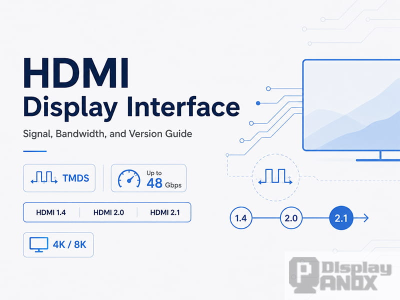
In HDMI 1.x and HDMI 2.0, high-speed video data is transmitted through TMDS, which stands for Transition Minimized Differential Signaling.
TMDS uses differential signaling. Instead of sending a signal through a single wire referenced to ground, it sends opposite signals through a pair of wires. The receiver reads the difference between the two signals. This method helps improve noise resistance and signal stability, especially at high data rates.
For standard RGB video, HDMI uses three TMDS data channels. Each channel carries one color component or related data stream. Together, they transmit the pixel information required to form the image on the display.
A simplified HDMI signal flow looks like this:
| Step | What Happens |
|---|---|
| 1 | The source device detects the connected display through Hot Plug Detect |
| 2 | The source reads the display’s EDID data through DDC |
| 3 | The source selects a supported resolution, refresh rate, and color format |
| 4 | Video data is encoded and transmitted through TMDS or FRL, depending on the HDMI version and mode |
| 5 | The display or driver board decodes the signal and drives the panel |
For PanoxDisplay solution projects, this process is often handled by an HDMI driver board. The board receives the HDMI signal from the host device and converts it into the interface required by the display panel, such as MIPI, LVDS, RGB, or eDP.
4. Why TMDS Encoding Is Needed
Digital video signals may look simple from the outside, but high-speed transmission is not just about sending 0s and 1s. If the signal contains too many continuous 0s or 1s, or if the number of 0s and 1s is poorly balanced, several problems can appear:
-
The signal baseline may drift.
-
Electromagnetic interference may increase.
-
The receiver may have more difficulty maintaining stable data interpretation.
-
Long cables may become less reliable.
TMDS encoding was designed to reduce these problems.
In TMDS-based HDMI transmission, 8-bit video data is converted into a 10-bit code. This is often described as an 8b/10b-style process, but TMDS has its own specific encoding method. The goal is to minimize signal transitions while also helping maintain DC balance.
The basic idea is:
| Purpose | Benefit |
|---|---|
| Reduce unnecessary transitions | Helps lower electromagnetic interference |
| Maintain DC balance | Helps prevent signal baseline drift |
| Improve transmission stability | Makes high-speed digital video more reliable |
| Add structured coding | Helps the receiver identify valid signal patterns |
Because 8 bits of video data are transmitted as 10-bit symbols, TMDS has a 25% coding overhead. In simple terms, only about 80% of the raw TMDS link rate is available for actual video payload before considering other timing and format factors.
This is why HDMI bandwidth numbers must be interpreted carefully. A port labeled with a certain raw bandwidth does not mean the entire bandwidth is available for visible image data.
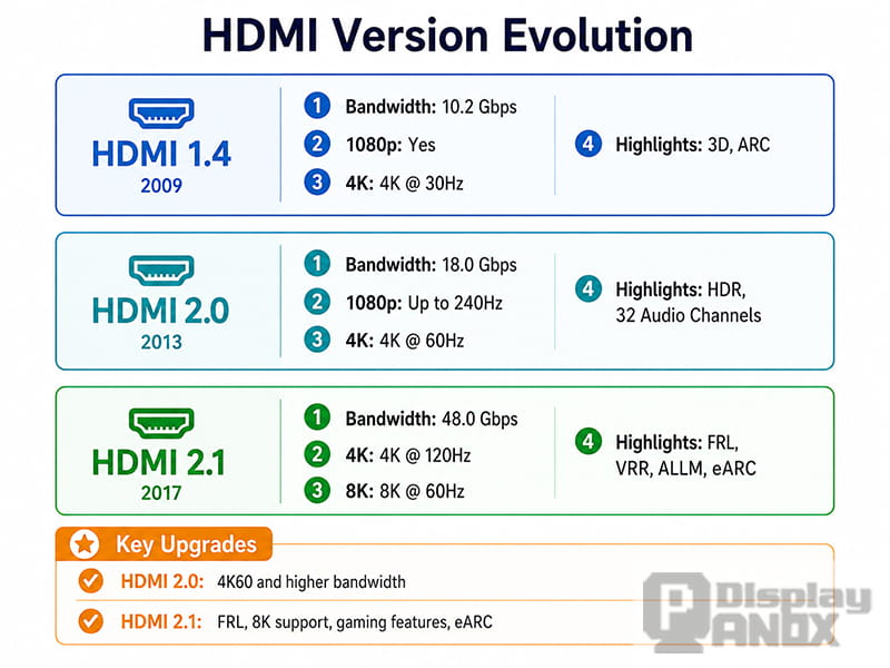
5. HDMI Versions and Bandwidth Evolution
HDMI has gone through several important version updates. Each major upgrade was driven by the need for higher resolution, higher refresh rate, deeper color, better audio, and more advanced display features.
A simplified version comparison is shown below:
| HDMI Version | Maximum Bandwidth | Typical Display Capability | Key Notes |
|---|---|---|---|
| HDMI 1.4 | 10.2 Gbps | Up to 4K at 30Hz in common use cases | Suitable for 1080p and basic 4K applications |
| HDMI 2.0 | 18 Gbps | 4K at 60Hz, depending on color depth and format | Common for 4K displays, media players, and industrial display systems |
| HDMI 2.1 | 48 Gbps | 4K at 120Hz, 8K at 60Hz in supported configurations | Introduces FRL, VRR, ALLM, eARC, and stronger gaming/AV features |
| HDMI 2.2 | 96 Gbps | Designed for next-generation high-resolution and high-refresh applications | Introduces Ultra96 cable support and higher-bandwidth FRL operation |
For most current display solution projects, HDMI 1.4, HDMI 2.0, and HDMI 2.1 are still the most relevant versions. HDMI 2.2 is important for future-facing applications, but its adoption depends on source devices, cables, chipsets, and display hardware support.
6. HDMI 2.1: Why It Was a Major Upgrade
HDMI 2.1 was a major step forward because it moved beyond the limitations of traditional TMDS transmission for high-bandwidth modes.
The most important change is FRL, or Fixed Rate Link. FRL replaces TMDS in high-speed HDMI 2.1 modes and allows much higher data rates. This makes HDMI 2.1 suitable for demanding applications such as 4K high-refresh gaming, 8K video, advanced AV receivers, and large-format displays.
Key HDMI 2.1 features include:
| Feature | Meaning |
|---|---|
| FRL | A higher-speed link mode that replaces TMDS for advanced bandwidth requirements |
| 48 Gbps Bandwidth | Enables much higher resolution and refresh rate combinations |
| DSC | Display Stream Compression, used to reduce bandwidth requirements while maintaining visually lossless quality |
| VRR | Variable Refresh Rate, useful for smoother gaming and reduced screen tearing |
| ALLM | Auto Low Latency Mode, useful for game consoles and low-latency display applications |
| eARC | Enhanced Audio Return Channel for high-quality audio return in AV systems |
| Dynamic HDR Support | Allows HDR information to be adjusted scene by scene or frame by frame in supported systems |
One practical point is important: not every device labeled “HDMI 2.1” supports the full 48 Gbps bandwidth or all HDMI 2.1 features. For engineering and purchasing decisions, the actual supported bandwidth, resolution, refresh rate, color depth, and feature list should always be checked.
7. How to Estimate HDMI Bandwidth Requirements
A display interface must provide enough bandwidth for the target resolution, refresh rate, color depth, and signal format.
A simplified bandwidth estimate can be calculated as:
Required video data rate = horizontal pixels × vertical pixels × refresh rate × bits per pixel
For RGB 8-bit color, each pixel uses 24 bits: 8 bits for red, 8 bits for green, and 8 bits for blue.
However, real HDMI bandwidth planning must also consider:
-
TMDS encoding overhead in HDMI 1.x and HDMI 2.0
-
Blanking intervals in the video timing
-
Color depth, such as 8-bit, 10-bit, or 12-bit
-
Chroma format, such as RGB, YCbCr 4:4:4, 4:2:2, or 4:2:0
-
DSC compression in supported HDMI 2.1 or newer systems
-
Cable quality and signal integrity margin
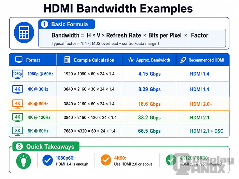
The following table gives a practical reference for common display formats:
| Display Format | Typical Requirement | Recommended HDMI Version |
|---|---|---|
| 1920×1080 at 60Hz | Easy for modern HDMI systems | HDMI 1.4 or above |
| 2560×1440 at 60Hz | Usually supported by HDMI 1.4/2.0 depending on timing | HDMI 1.4 or HDMI 2.0 |
| 3840×2160 at 30Hz | Basic 4K support | HDMI 1.4 or above |
| 3840×2160 at 60Hz, 8-bit RGB | Common 4K60 requirement | HDMI 2.0 or above |
| 3840×2160 at 60Hz, 10-bit HDR | May require HDMI 2.0 with reduced chroma or HDMI 2.1 | HDMI 2.0/2.1 depending on format |
| 3840×2160 at 120Hz | High-refresh 4K application | HDMI 2.1 recommended |
| 7680×4320 at 60Hz | 8K application, often requires FRL and/or DSC | HDMI 2.1 or above |
For a display product, the required HDMI version should not be chosen by resolution alone. Refresh rate, color depth, and the host device’s output format matter just as much.
For example, a 4K panel running at 30Hz may work with HDMI 1.4, while the same panel running at 60Hz generally requires HDMI 2.0. If 10-bit color or high-refresh operation is required, HDMI 2.1 may become necessary.
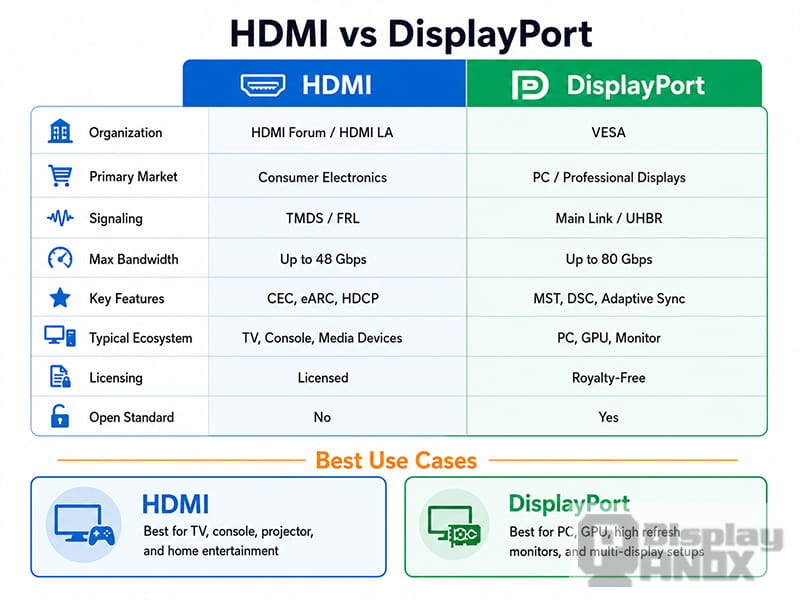
8. HDMI vs DisplayPort
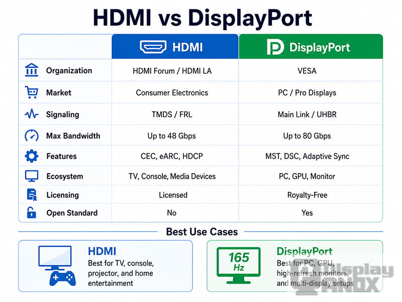
HDMI and DisplayPort are both high-performance digital display interfaces, but they are commonly used in different product ecosystems.
HDMI is dominant in televisions, projectors, game consoles, AV receivers, media players, and many embedded display driver boards. DisplayPort is widely used in PC monitors, graphics cards, professional workstations, and USB-C display output.
A practical comparison is shown below:
| Category | HDMI | DisplayPort |
|---|---|---|
| Main Ecosystem | TV, projector, game console, AV, embedded display board | PC monitor, graphics card, workstation, USB-C display |
| Audio Support | Strong AV ecosystem, ARC/eARC support | Supports audio, but less focused on home theater |
| Device Control | CEC support for compatible devices | Not typically used for consumer device control |
| Multi-Monitor Use | Possible in some systems, but not its main strength | MST support makes multi-monitor setups easier |
| High-Bandwidth Versions | HDMI 2.1 up to 48 Gbps, HDMI 2.2 up to 96 Gbps | DisplayPort 2.1 up to 80 Gbps with UHBR20 |
| Typical Use Case | Plug-and-play display connection for broad compatibility | High-performance PC display connection |
For many industrial and commercial display applications, HDMI is selected because the host side is easy to support. A PC, Raspberry Pi, mini PC, media box, or testing instrument can output HDMI directly. This makes HDMI very useful for demos, evaluation kits, control panels, digital signage, and low-volume customized display solutions.
DisplayPort is often preferred when the application is strongly PC-centered, requires multi-monitor expansion, or depends on the latest GPU/display bandwidth features.
9. When to Choose an HDMI Display Solution
HDMI is a strong choice when a project needs simple connection, broad compatibility, and fast system integration.
Typical HDMI display solution applications include:
-
Raspberry Pi displays
-
Mini PC displays
-
Industrial control panels
-
Medical equipment monitors
-
Digital signage screens
-
Gaming and simulator displays
-
Projector and optical engine displays
-
Test equipment and development platforms
-
Portable monitors
-
Custom LCD/OLED demo kits
For these projects, the display panel itself may not have a native HDMI interface. Many LCD and OLED panels use internal interfaces such as MIPI DSI, LVDS, RGB, or eDP. In this case, an HDMI driver board becomes the bridge between the HDMI source and the panel.
PanoxDisplay can support display solution development by pairing suitable LCD, OLED, Micro OLED, or flexible display panels with matching driver boards. Depending on the panel and application, the solution may include HDMI-to-MIPI, HDMI-to-LVDS, HDMI-to-RGB, HDMI-to-eDP, or other customized interface conversion options.
10. HDMI Selection Checklist for Display Projects
Before selecting an HDMI display module or HDMI driver board, the following points should be confirmed:
| Item | Why It Matters |
|---|---|
| Resolution | Determines the basic pixel bandwidth requirement |
| Refresh Rate | Higher refresh rates greatly increase bandwidth demand |
| Color Depth | 10-bit and 12-bit color require more bandwidth than 8-bit |
| HDMI Version | Must match the required resolution, refresh rate, and features |
| Input Source | PC, media player, Raspberry Pi, camera, console, or custom host |
| Panel Interface | MIPI, LVDS, RGB, eDP, or other native panel interface |
| Touch Function | Some applications require USB touch, I2C touch, or custom touch control |
| Cable Length | Longer HDMI cables require better signal integrity |
| Power Design | Driver board and panel power requirements must be matched |
| Mechanical Space | Connector position, board size, and panel structure affect integration |
A stable HDMI display solution is not only about choosing a panel with the right size and resolution. The source device, HDMI version, driver board, firmware, cable, power supply, and mechanical design must work together.
11. Summary
HDMI remains one of the most practical display interfaces because it combines video, audio, control, compatibility, and plug-and-play convenience in one connection.
The core technical points are:
-
HDMI was developed as a digital audio-video interface and extended many ideas from DVI.
-
Standard HDMI Type-A uses 19 pins, including TMDS channels, DDC, CEC, +5V, and Hot Plug Detect.
-
HDMI 1.x and HDMI 2.0 use TMDS transmission, where 8-bit data is encoded into 10-bit symbols.
-
TMDS helps improve signal stability by reducing unnecessary transitions and maintaining better DC balance.
-
HDMI 2.1 introduced FRL for much higher bandwidth and advanced display features such as VRR, ALLM, DSC, and eARC.
-
HDMI 2.2 further increases the maximum bandwidth for next-generation display applications.
-
HDMI is especially useful for display solutions that need broad device compatibility and easy connection to common host systems.
-
DisplayPort remains strong in PC, GPU, workstation, and multi-monitor environments.
For custom LCD, OLED, Micro OLED, and embedded display projects, HDMI is often the most convenient interface for development, testing, demonstration, and end-product integration. With the right driver board and panel matching, HDMI can turn a native display panel into a practical plug-and-play display solution for a wide range of applications.
Learn more: HDMI Display Driver Framework on Linux: From DRM/KMS Architecture to Black Screen Debugging