


1. Why HDMI Driver Knowledge Matters in Embedded Display Projects
In an embedded display project, connecting an HDMI cable does not always mean the screen will light up immediately. A display may stay black because of a missing hot-plug signal, failed EDID reading, an incorrect pixel clock, a disabled encoder, a PHY configuration issue, or even an HDCP authentication problem.
For display module development, HDMI driver debugging is often where hardware design, Linux kernel configuration, and display timing knowledge meet. A clear understanding of the Linux HDMI display path can help engineers locate problems faster, especially when working with custom boards, HDMI display modules, controller boards, and industrial display solutions.
PanoxDisplay works with different display interfaces and display control boards, including HDMI-based display solutions. This article explains the HDMI driver framework in Linux from a practical engineering perspective: DRM/KMS architecture, HDMI connector logic, encoder and PHY setup, HDCP handling, audio transmission, and a step-by-step black screen debugging workflow.
hdmi connector flow
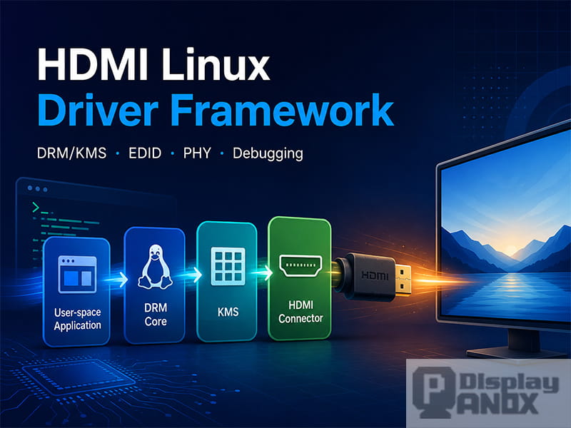
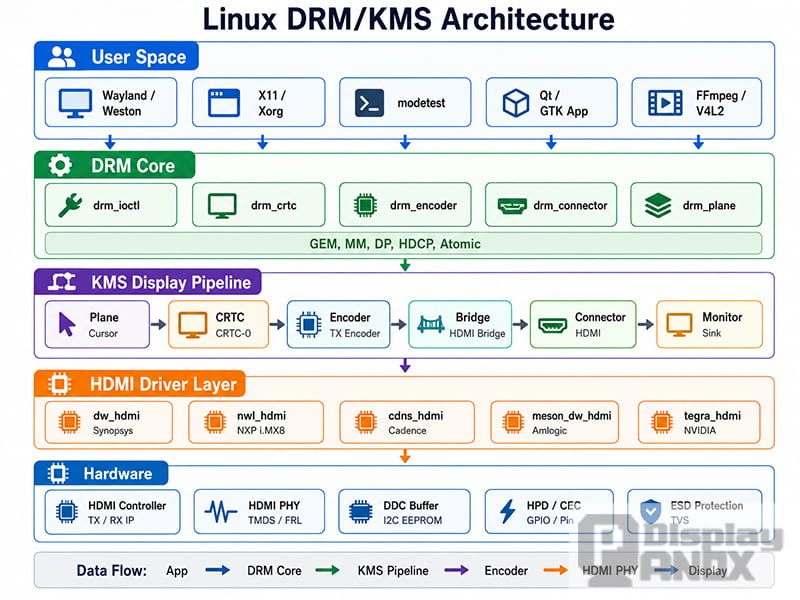
2. Linux Display Subsystem: DRM and KMS
Linux uses the DRM subsystem, short for Direct Rendering Manager, to manage graphics and display output. Within DRM, KMS, or Kernel Mode Setting, is responsible for setting display modes such as resolution, refresh rate, timing, framebuffer format, and output routing. The Linux kernel documentation describes the KMS display pipeline as a structure where framebuffers feed into planes, planes feed pixel data into a CRTC, and the output path continues through encoders and connectors.
For HDMI display output, the key point is simple: the screen does not receive an image from only one driver function. It depends on a complete display pipeline.
A typical DRM/KMS path looks like this:
Framebuffer → Plane → CRTC → Encoder → Bridge → Connector → HDMI Display
Each component has a different role.
2.1 Plane: The Image Layer
A plane manages the image buffer that will be scanned out to the display. It can be a primary plane, cursor plane, or overlay plane.
In simple display applications, the primary plane carries the main screen image. In more complex systems, overlay planes can be used for video layers, UI elements, or hardware composition.
2.2 CRTC: The Timing Controller
The CRTC controls the display scanout process. It handles timing parameters such as resolution, horizontal sync, vertical sync, refresh rate, and pixel clock.
If the CRTC is not configured with a valid display mode, the HDMI output cannot generate a stable image.
2.3 Encoder: The Signal Converter
The encoder connects the internal display pipeline to a physical output type. In an HDMI system, it prepares the display stream for HDMI transmission.
The Linux DRM documentation notes that encoders are part of the KMS output routing model and are connected between the CRTC and connector.
2.4 Bridge: The Optional Conversion Stage
A bridge is an intermediate chip or IP block used to convert one display interface into another.
Common examples include:
| Bridge Type | Typical Use |
|---|---|
| HDMI to MIPI | Driving a MIPI panel from an HDMI source |
| RGB to HDMI | Converting parallel RGB output to HDMI |
| LVDS to HDMI | Converting LVDS display output to HDMI |
| eDP to HDMI | Using eDP source output with HDMI display devices |
Not every HDMI design uses a bridge. Some SoCs integrate HDMI output directly.
2.5 Connector: The Physical Output Interface
The connector represents the actual output interface, such as HDMI-A, DisplayPort, VGA, or eDP.
For HDMI, the connector is responsible for:
| Function | Meaning |
|---|---|
| HPD detection | Detecting whether an HDMI device is plugged in |
| EDID reading | Reading display capability information |
| Mode list generation | Creating available resolutions and refresh rates |
| Content protection state | Managing HDCP-related properties |
| User-space reporting | Exposing connector status to applications and tools |
In practical debugging, the HDMI connector is usually the first place to check.
3. Atomic Commit: Applying Display State Safely
Modern DRM drivers use atomic mode setting. The idea is that multiple display changes are checked and applied together.
For example, a mode change may include:
| State Change | Example |
|---|---|
| CRTC mode | 1920 × 1080 at 60 Hz |
| Plane position | Full-screen primary plane |
| Framebuffer format | XRGB8888 |
| Encoder routing | CRTC connected to HDMI encoder |
| Connector state | HDMI-A-1 enabled |
With atomic commit, the kernel checks whether the complete configuration is valid before applying it. If the configuration cannot work, it should fail as a whole instead of leaving the display pipeline in a half-configured state.
Typical helper functions include:
drm_atomic_helper_check();
drm_atomic_helper_commit();
For HDMI debugging, this means a black screen may not be caused by only the final HDMI output stage. The atomic check may fail earlier because the mode, plane format, bridge chain, or connector routing is invalid.
drm kms architecture
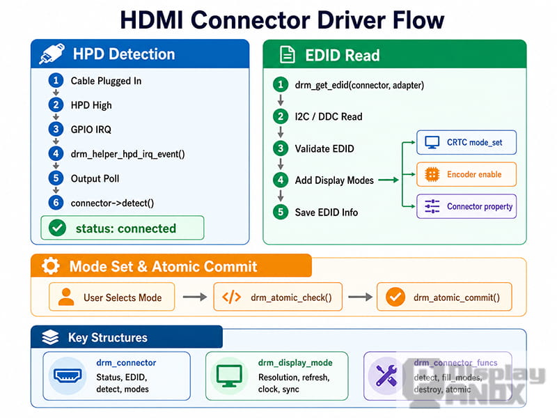
4. HDMI Connector Driver: Detecting the Display
The HDMI connector is the external-facing part of the driver. It detects cable insertion, reads EDID, reports connection status, and exposes supported display modes.
4.1 HPD: Hot Plug Detection
HPD stands for Hot Plug Detect. When an HDMI cable is connected or disconnected, the HPD pin changes state. The Linux driver usually captures this event through GPIO interrupt handling or an SoC-specific HDMI interrupt.
A typical HPD flow looks like this:
-
HDMI cable is inserted.
-
HPD pin level changes.
-
GPIO or HDMI interrupt is triggered.
-
The driver calls the DRM hot-plug event handler.
-
The connector detect callback is executed.
-
The kernel reports the connector as connected.
-
EDID is read through the DDC channel.
-
Display modes are created and exposed to user space.
A common DRM helper call is:
drm_helper_hpd_irq_event(dev);
If HPD never triggers, check these points first:
| Check Item | Possible Issue |
|---|---|
| Device tree configuration | Wrong HPD GPIO definition |
| GPIO interrupt | Interrupt not registered or wrong trigger edge |
| Pull-up resistor | Missing or incorrect HPD pull-up |
| HDMI cable | Cable does not carry the HPD signal properly |
| Connector soldering | HPD pin not connected correctly |
For many embedded boards, HPD problems are among the most common reasons why an HDMI monitor is not detected.
4.2 EDID Reading Through DDC
After HDMI connection is detected, the system reads EDID from the display device. EDID stands for Extended Display Identification Data. It tells the source device what resolutions, refresh rates, color formats, audio formats, and other capabilities the display supports.
EDID is usually read through the DDC channel, which is based on I2C. The EDID device address is commonly 0x50.
A simplified EDID reading flow:
drm_get_edid(connector, adapter);
i2c_transfer();
drm_edid_block_valid();
drm_add_edid_modes();
Useful debug commands:
cat /sys/class/drm/card0-HDMI-A-1/edid | edid-decode
Or view the raw data:
hexdump -C /sys/class/drm/card0-HDMI-A-1/edid | head -20
If EDID cannot be read, check:
| Problem | Debug Direction |
|---|---|
| EDID file is empty | DDC not working |
| EDID data is all zeros | I2C pull-up or wiring issue |
| EDID checksum error | Signal integrity or unstable DDC communication |
| Mode list is empty | EDID parsing failed |
| Only low resolutions appear | Display or adapter reports limited capability |
DDC lines usually require proper pull-up resistors. On many hardware designs, SCL and SDA use pull-ups such as 4.7 kΩ, but the actual value should follow the board design and chip vendor recommendation.
4.3 Connector Callback Functions
In a Linux DRM HDMI driver, the connector communicates with the DRM core through callback functions.
Common connector callbacks include:
| Callback | Purpose | Typical Trigger |
|---|---|---|
detect() |
Detect whether HDMI is connected | HPD event or user query |
fill_modes() |
Add supported display modes | First connection or mode refresh |
atomic_get_property() |
Read connector property | User-space query |
atomic_set_property() |
Set connector property | Atomic commit |
destroy() |
Release connector resources | Driver unload |
A typical connector function structure may look like this:
static const struct drm_connector_funcs hdmi_connector_funcs = {
    .detect = hdmi_connector_detect,
    .fill_modes = drm_helper_probe_single_connector_modes,
    .destroy = drm_connector_cleanup,
    .atomic_get_property = hdmi_atomic_get_property,
    .atomic_set_property = hdmi_atomic_set_property,
};
For debugging, the detect() and EDID-related functions are especially important because they determine whether user space can even see the HDMI display as an available output.
5. HDMI Encoder and PHY Configuration
After the connector detects a display and the DRM pipeline chooses a mode, the HDMI encoder and PHY must generate the correct signal.
The encoder prepares the video data for HDMI transmission. The PHY converts internal digital signals into high-speed differential electrical signals.
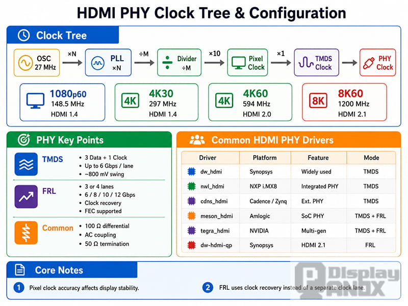
5.1 Clock Path: From Reference Clock to TMDS Clock
HDMI output depends heavily on clock accuracy. If the pixel clock is wrong, the monitor may show a black screen, flickering, unstable image, or “out of range” warning.
A typical HDMI clock path includes:
-
Reference oscillator
-
PLL multiplier
-
Clock divider
-
Pixel clock
-
TMDS character clock
-
PHY serial clock
-
Differential HDMI output
Common pixel clock examples:
| Display Mode | Typical Pixel Clock | Common HDMI Requirement |
|---|---|---|
| 1280 × 720 @ 60 Hz | 74.25 MHz | HDMI 1.4 class output |
| 1920 × 1080 @ 60 Hz | 148.5 MHz | HDMI 1.4 class output |
| 3840 × 2160 @ 30 Hz | 297 MHz | HDMI 1.4 class output |
| 3840 × 2160 @ 60 Hz | 594 MHz | HDMI 2.0 class output |
In real projects, the exact clock depends on timing parameters, blanking intervals, color depth, and the selected video standard.
For custom display solutions, clock configuration should not be guessed. It must match the mode timing, the SoC HDMI IP capability, the PHY capability, and the display sink capability.
5.2 TMDS and FRL
HDMI 2.0 and earlier systems commonly use TMDS transmission. TMDS uses differential pairs to send video data and clock information.
Newer HDMI specifications introduce FRL, or Fixed Rate Link, for higher-bandwidth modes. HDMI Licensing describes FRL as a signaling technology used for higher bandwidth HDMI specifications, with HDMI 2.2 supporting up to 96 Gbps and the Ultra High Speed HDMI Cable from HDMI 2.1 supporting up to 48 Gbps maximum bandwidth.
A practical comparison:
| Item | TMDS | FRL |
|---|---|---|
| Common HDMI generation | HDMI 2.0 and earlier | HDMI 2.1 and newer high-bandwidth modes |
| Clock structure | Uses a separate clock channel | Clock recovered from data |
| Encoding overhead | Higher than FRL | More efficient for high bandwidth |
| Typical use | 1080p, 4K30, 4K60 depending on version | 4K120, 8K, higher refresh and color depth |
| Driver concern | Pixel clock and TMDS rate | Link training and lane rate |
For many embedded HDMI display modules and industrial display projects, TMDS is still the most common mode. FRL becomes more important when the application requires very high resolution, high refresh rate, deep color, or advanced HDMI 2.1/2.2 features.
5.3 HDMI PHY Configuration
The PHY is where digital display configuration becomes real electrical output.
Important PHY parameters include:
| Parameter | Why It Matters |
|---|---|
| PLL lock | Without PLL lock, no stable output clock is available |
| Differential swing | Incorrect voltage swing may cause unstable display |
| Pre-emphasis | Helps compensate high-speed signal loss |
| Impedance | HDMI differential pairs should be controlled carefully |
| Lane mapping | Wrong mapping causes no image or corrupted image |
| Power sequence | Some PHYs require strict enable order |
PHY debugging often requires both software and hardware tools. Kernel logs may show whether the PLL is locked, but a high-speed oscilloscope or eye diagram test may be needed to confirm signal quality.
5.4 Common HDMI Driver Blocks
Different SoC platforms use different HDMI drivers or IP blocks. Common examples include:
| Driver / IP Name | Platform or Vendor | Notes |
|---|---|---|
dw_hdmi |
Synopsys DesignWare HDMI | Widely used in embedded Linux platforms |
nwl_hdmi |
NXP i.MX8 series | Integrated HDMI controller |
cdns_hdmi |
Cadence-based platforms | Common in some FPGA/SoC designs |
meson_hdmi |
Amlogic platforms | Used in Amlogic SoCs |
tegra_hdmi |
NVIDIA Tegra platforms | Used across Tegra generations |
dw-hdmi-qp |
Newer Synopsys HDMI IP | Used for newer HDMI architectures |
The exact debug path depends on the SoC, kernel version, device tree, and board design. However, the general logic remains similar: connector detection, EDID reading, mode selection, encoder enable, PHY configuration, and signal output.
phy clock config
6. HDCP in Linux HDMI Output
HDCP stands for High-bandwidth Digital Content Protection. It is used to protect video content transmitted through digital display interfaces such as HDMI and DisplayPort.
In Linux DRM, content protection is exposed through connector properties. The DRM content protection property is attached to a connector and allows user space to request link protection. The property can report states such as Undesired, Desired, and Enabled.
6.1 Content Protection States
A simplified explanation:
| State | Meaning |
|---|---|
| Undesired | Content protection is not requested |
| Desired | User space requests protection, but it is not active yet |
| Enabled | Protection is active and the link is protected |
Only the driver can report the final protected state. If the link fails authentication, the connector may remain in the Desired state instead of becoming Enabled.
6.2 HDCP 2.2 Authentication Flow
HDCP 2.2 authentication is more complex than HDCP 1.4. A simplified flow includes:
-
Authentication and key exchange starts.
-
The source verifies the receiver.
-
Locality check confirms that the receiver is physically connected.
-
A session key is exchanged.
-
Encryption starts.
-
If repeaters are used, topology verification is performed.
In kernel driver debugging, HDCP failures are usually related to:
| Failure Area | Possible Cause |
|---|---|
| Version mismatch | Source and sink do not support the same HDCP version |
| Key issue | HDCP keys are missing or not provisioned |
| Repeater issue | HDMI splitter, capture device, or converter causes authentication failure |
| Firmware issue | Required firmware component is missing |
| Link instability | HDMI signal is not stable enough for authentication |
Useful command:
cat /sys/class/drm/card0-HDMI-A-1/properties/content_protection
Typical kernel log patterns:
dmesg | grep -i hdcp
Possible logs may include:
hdcp: authentication failed
hdcp: authenticated successfully
hdcp: link check failed
In industrial or embedded display applications, HDCP is not always required. If the screen is used for UI, HMI, instrumentation, or machine control, HDCP may not be involved. However, for media playback, protected video content, set-top boxes, or consumer HDMI products, HDCP support may become important.
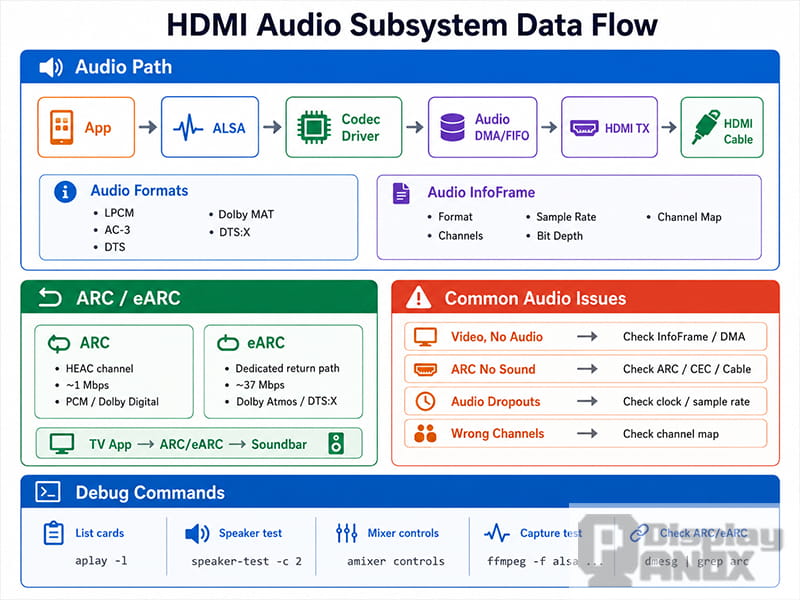
7. HDMI Audio Configuration
HDMI can transmit both video and audio. In Linux, HDMI audio usually involves cooperation between the ALSA audio subsystem and the DRM display framework.
A simplified HDMI audio path:
-
The application outputs PCM audio through ALSA.
-
The audio driver writes data into DMA or FIFO buffers.
-
The HDMI controller packages audio data into HDMI data islands.
-
Audio InfoFrame packets describe the audio format.
-
The receiving device decodes and plays the audio.
7.1 Audio InfoFrame
The Audio InfoFrame works like a small description packet. It tells the HDMI sink what kind of audio data is being transmitted.
Common fields include:
| Field | Example |
|---|---|
| Audio format | LPCM, AC-3, DTS, MPEG-AAC |
| Channel count | 2 channels, 4 channels, 6 channels, 8 channels |
| Sampling frequency | 32 kHz, 44.1 kHz, 48 kHz, 96 kHz, 192 kHz |
| Sample size | 16-bit, 20-bit, 24-bit |
| Speaker allocation | Front left/right, center, surround, LFE |
If the video works but audio is missing, Audio InfoFrame configuration should be checked together with ALSA device selection and HDMI sink capability.
7.2 ARC and eARC
ARC means Audio Return Channel. It allows a TV to send audio back to an audio device such as a soundbar through the HDMI cable.
eARC, or Enhanced Audio Return Channel, is a newer version with higher audio bandwidth and better support for advanced audio formats.
| Feature | ARC | eARC |
|---|---|---|
| HDMI generation | Introduced with HDMI 1.4 | Associated with HDMI 2.1 and newer systems |
| Typical bandwidth | Lower | Higher |
| Advanced audio formats | Limited | Better support |
| Common use | TV to soundbar audio return | High-quality home theater audio return |
For embedded display modules and industrial monitors, ARC and eARC are usually not the core requirement. For consumer display systems, smart displays, and multimedia products, they may become part of the total HDMI solution.
7.3 Common HDMI Audio Problems
| Symptom | Possible Cause | Debug Direction |
|---|---|---|
| Video works but no sound | Wrong ALSA device or missing InfoFrame | Check ALSA routing and HDMI audio setup |
| Audio is intermittent | Sample rate mismatch or unstable clock | Try 48 kHz and check clock configuration |
| Wrong channel output | Incorrect channel allocation | Check Audio InfoFrame |
| ARC has no sound | ARC not enabled or cable issue | Check TV setting, HDMI port, and CEC-related wiring |
| Audio device not listed | Driver registration issue | Check ALSA card and kernel logs |
audio subsystem
8. Practical Debugging: From Black Screen to Display Output
When a new board is connected to an HDMI display and the screen stays black, debugging should follow a structured path. Randomly changing kernel settings often wastes time and may introduce new problems.
The following seven-step workflow can help narrow down the issue.
8.1 Step 1: Check HPD Detection
Run:
dmesg | grep -i hpd
Also check connector status:
cat /sys/class/drm/card0-HDMI-A-1/status
Expected result:
connected
If the result is:
disconnected
Check:
| Item | Action |
|---|---|
| HDMI cable | Try another cable |
| HDMI monitor | Try another display |
| HPD GPIO | Verify device tree configuration |
| Interrupt | Confirm interrupt registration |
| Pull-up | Check HPD pull-up resistor |
| Connector | Inspect soldering and pin connection |
8.2 Step 2: Read EDID
Run:
cat /sys/class/drm/card0-HDMI-A-1/edid | edid-decode
If edid-decode is not installed, use:
hexdump -C /sys/class/drm/card0-HDMI-A-1/edid | head -20
If EDID reading fails, check:
| Item | Action |
|---|---|
| DDC SCL/SDA | Confirm correct routing |
| I2C address | Check access to address 0x50 |
| Pull-up resistors | Verify SCL and SDA pull-ups |
| Level shifting | Check voltage compatibility |
| Cable or adapter | Remove unnecessary adapters |
If EDID is valid, the system should be able to generate a list of supported display modes.
8.3 Step 3: Inspect DRM Connectors and Modes
modetest is a useful DRM/KMS diagnostic tool. It can list connectors, encoders, CRTCs, planes, and supported modes, and it can also set display modes directly.
List connectors:
modetest -M <driver_name> -c
Example:
modetest -M rockchip -c
Look for:
| Field | What to Check |
|---|---|
| Connector ID | Required for mode setting |
| Connector status | Connected or disconnected |
| Supported modes | Resolution and refresh rate list |
| Encoder ID | Whether connector has an encoder |
| Preferred mode | Usually from EDID |
If no modes appear, EDID or connector detection is still not working correctly.
8.4 Step 4: Check CRTC Binding
List CRTCs and planes:
modetest -M <driver_name> -p
The goal is to confirm that a valid CRTC is available and can be routed to the HDMI connector.
Possible issues:
| Issue | Meaning |
|---|---|
| No available CRTC | Display pipeline is not registered correctly |
| Plane format mismatch | Framebuffer format not supported |
| CRTC cannot route to encoder | Device tree or driver routing issue |
| Atomic check fails | Mode or pipeline state is invalid |
8.5 Step 5: Confirm Encoder Enable
Check encoder-related logs:
dmesg | grep -i encoder
Also check DRM logs if dynamic debug is enabled.
If the encoder is not enabled, possible causes include:
| Cause | Explanation |
|---|---|
| Atomic commit failed | Display state was rejected |
| Wrong display route | CRTC and encoder are not connected correctly |
| Bridge chain issue | Intermediate bridge failed to attach |
| Missing power domain | HDMI IP block is not powered |
| Clock not enabled | Required HDMI clocks are disabled |
8.6 Step 6: Check PHY and Signal Output
If HPD and EDID work, and the encoder is enabled, but the display is still black, the PHY becomes a key debug area.
Check:
| Item | Method |
|---|---|
| PLL lock | Read PHY or HDMI status register |
| TMDS output | Measure differential signal |
| Impedance | Review PCB differential pair design |
| Eye diagram | Use proper high-speed test equipment |
| Power sequence | Check vendor driver requirements |
| Lane mapping | Confirm schematic and driver mapping |
A screen that flickers or shows random noise often points to clock accuracy or signal integrity rather than pure software configuration.
8.7 Step 7: Force a Display Mode with modetest
When the basic path looks correct, force a mode directly through DRM/KMS.
Example:
sudo modetest -M <driver_name> -s <connector_id>:1920x1080-60
Some platforms also support atomic mode setting through:
sudo modetest -M <driver_name> -a -s <connector_id>:1920x1080-60
This bypasses a full desktop environment and tests the DRM driver more directly.
If forced mode setting works, but the normal system UI does not display, the issue may be in user space, such as Wayland, X11, framebuffer configuration, Qt, or application-level display selection.
9. Quick Troubleshooting Table
| Symptom | Possible Cause | Recommended Debug Path |
|---|---|---|
| HDMI not detected | HPD GPIO, interrupt, cable, connector issue | Check /status, HPD logs, GPIO configuration |
| EDID cannot be read | DDC I2C wiring or pull-up issue | Check EDID file, I2C address, SCL/SDA signals |
| Mode list is empty | EDID parsing failure | Decode EDID and inspect DRM connector modes |
| Screen is black | Encoder, CRTC, bridge, or PHY issue | Check modetest output and kernel logs |
| Image flickers | Pixel clock or PHY instability | Check PLL lock and signal quality |
| Wrong resolution | EDID or preferred mode issue | Force mode with modetest |
| Video works but no audio | ALSA routing or Audio InfoFrame issue | Check ALSA device and HDMI audio configuration |
| HDCP stuck in Desired | Authentication failed | Check sink support, keys, repeaters, and direct connection |
| 4K output unstable | Bandwidth or PHY limitation | Reduce resolution/refresh rate and verify PHY capability |
| Works on one monitor only | EDID compatibility or timing tolerance | Compare EDID from both displays |
10. Design Notes for HDMI Display Solutions
For HDMI display products, driver debugging should not be separated from hardware design. A stable HDMI display solution depends on the full chain.
Important design points include:
| Area | Design Consideration |
|---|---|
| Display panel | Resolution, timing, brightness, interface, operating temperature |
| Controller board | HDMI input capability, scaling, firmware, power design |
| HDMI connector | Mechanical reliability and signal integrity |
| DDC channel | Correct I2C routing and pull-up design |
| HPD signal | Proper GPIO or HDMI IP connection |
| Power sequence | Panel, backlight, controller board, and HDMI IP timing |
| EMI control | Differential pair layout, shielding, grounding |
| Software support | Linux driver, device tree, display mode configuration |
For projects using custom display sizes, high-brightness LCD modules, long strip displays, OLED panels, or HDMI controller boards, early verification is important. A display may look like a simple output device, but the actual signal path includes hardware timing, kernel driver state, and user-space display configuration.
PanoxDisplay can support display module selection and HDMI-based display solution matching for embedded devices, industrial control systems, smart hardware, portable monitors, and custom display applications.
11. Conclusion
HDMI display output on Linux is not a single switch. It is a complete display pipeline built from DRM/KMS objects, connector detection, EDID reading, encoder routing, PHY signal output, optional HDCP protection, and audio configuration.
When a screen does not light up, the most efficient method is to debug in order:
-
Confirm HDMI connection and HPD.
-
Read and decode EDID.
-
Inspect DRM connector modes.
-
Check CRTC and encoder routing.
-
Verify PHY clock and signal output.
-
Check HDCP if protected content is involved.
-
Use modetest to force a known display mode.
For embedded display development, this workflow turns “the screen is black” from a vague problem into a traceable engineering path. A clear HDMI driver framework also helps hardware engineers, Linux driver developers, and display solution providers work from the same map instead of debugging in separate directions.
Learn more: HDMI Display Interface Explained: Signal Principles, Bandwidth, Versions, and Display Solution Selection