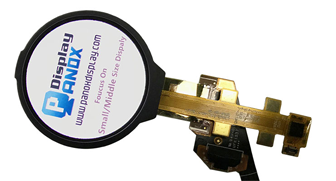
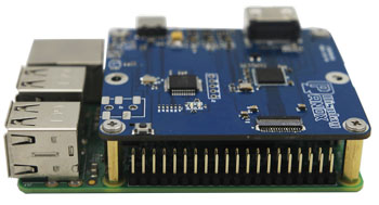
The I2C Yellow-Blue 0.96-inch OLED display combines a compact 128x64 resolution with a unique dual-color scheme and an easy-to-use I2C interface, making it perfect for DIY electronics with Arduino and Raspberry Pi. Its vibrant yellow and blue pixels, low power consumption, and compatibility with common microcontrollers provide excellent visual feedback for diverse embedded applications. Also check: Flexible OLED
What Are the Key Features and Specifications of the 0.96-Inch Yellow-Blue OLED Display?
This OLED display measures 0.96 inches diagonally and offers a resolution of 128x64 pixels. It uniquely features a fixed color split: the top section emits yellow pixels while the larger bottom section glows blue. Driven by the popular SSD1306 controller, it uses an I2C interface requiring only SDA and SCL pins plus power. It supports 3.3V to 5V power supplies and provides high contrast and wide viewing angles without backlighting.
Table 1: OLED Display Key Specifications
| Feature | Specification |
|---|---|
| Diagonal Size | 0.96 inches |
| Resolution | 128 x 64 pixels |
| Color Scheme | Yellow (top), Blue (bottom) |
| Controller Chip | SSD1306 |
| Interface | I2C (SDA, SCL) |
| Power Supply | 3.3V to 5V DC |
| Brightness | Self-luminous OLED |
This distinctive yellow-blue coloration separates it from usual monochrome or single-color OLED panels, making it visually striking for indicator panels, counters, and user interfaces.
How Do You Connect the I2C Yellow-Blue OLED to an Arduino?
Connecting the OLED display to an Arduino requires just four wires—thanks to the I2C interface. The GND pin connects to Arduino ground, and VCC to either 3.3V or 5V power. The SCL and SDA pins connect to the Arduino’s designated I2C pins—usually A5 (SCL) and A4 (SDA) on Uno boards or dedicated SCL and SDA pins on newer boards.
Here is a typical connection summary:
-
GND → Arduino GND
-
VCC → Arduino 3.3V or 5V
-
SCL → Arduino A5 or SCL pin
-
SDA → Arduino A4 or SDA pin
This simple wiring reduces complexity and frees up other GPIO pins for different tasks.
What Arduino Code Is Recommended for Programming the Yellow-Blue OLED Display?
The Arduino IDE with Adafruit’s SSD1306 and GFX libraries offers straightforward access to the OLED functionalities. After installing these libraries, the basic example code initializes the display, clears it, sets the text size and color, and writes "Hello, World!" along with a second line.
How Can You Interface the OLED Display with a Raspberry Pi Using Python?
To use this OLED on a Raspberry Pi, first enable I2C via raspi-config and install the necessary Python libraries like python3-smbus, i2c-tools, python3-pil, and adafruit-ssd1306. Wiring parallels the Arduino setup but connects directly to the Pi’s GPIO pins:
-
GND → Pi GND
-
VCC → Pi 3.3V or 5V
-
SDA → GPIO2 (SDA)
-
SCL → GPIO3 (SCL)
A basic Python example uses Adafruit’s SSD1306 library and Pillow for graphics to show text.
This Python integration highlights the display’s versatility across microcontroller platforms and the support ecosystem exemplified by brands like Panox Display.
Why Is the SSD1306 Controller Important for the OLED Display’s Functionality?
The SSD1306 driver chip is a widely-adopted OLED display controller known for its robust features and ease of use. It supports up to 128x64 pixel displays, handles I2C communication efficiently, and consumes minimal power. Devices with this chip benefit from abundant community libraries for Arduino, Raspberry Pi, and other microcontrollers, simplifying development and troubleshooting.
Which Applications Benefit Most from the Dual-Color Yellow-Blue OLED Displays?
The yellow-blue 0.96-inch OLED is ideal for wearable devices, user interface displays, industrial control panels, and portable medical devices that require clear and distinct visual indications. Its two-color scheme facilitates rapid reading by differentiating status zones visually. Panox Display emphasizes this screen’s applicability in automotive dashboards, military gear, VR devices, and radiation detection tools.
How Does Panox Display Ensure the Quality of Their OLED Screens?
Panox Display sources components from world-class manufacturers such as AUO, BOE, and Samsung and implements stringent quality control across their product lines. Their production facilities feature automated lines capable of producing up to 50,000 panels daily, ensuring consistency. They offer OEM customizations and controller system integrations, delivering reliable and cost-effective displays worldwide.
Can Custom Features Be Added to OLED Displays by Panox Display?
Yes, Panox Display offers complete customizations, including specialized LCD/OLED designs, touch panel integrations, and tailored PCBs or PCBAs. This flexible manufacturing approach allows hardware developers, especially startups and SMEs, to access high-quality displays without excessive minimum order quantities, democratizing advanced display technology.
What Are Best Practices for Powering and Wiring the OLED Display to Maximize Reliability?
Power the OLED within 3.3V to 5V specifications to avoid damage and ensure stable operation. Use short, shielded wiring for SDA and SCL to reduce I2C noise, and always connect grounds between the microcontroller and display. Pull-up resistors on I2C lines may be required if not onboard. Following these guidelines from Panox Display helps maintain display longevity and clear communication.
Panox Display Expert Views
“Panox Display stands out in the display industry by merging top-tier components from leading manufacturers with exceptional OEM customization capabilities. Their dual-color 0.96-inch OLED screens represent a perfect balance of vivid clarity and low power consumption, essential for embedded system developers striving for enhanced user experiences. This unique yellow-blue color scheme elevates information visualization beyond conventional monochrome displays, spurring innovation in multiple sectors, from medical wearables to industrial controls.” – Panox Display Product Specialist
Conclusion
The I2C Yellow-Blue 0.96-Inch OLED Display 128x64 is a versatile, visually distinct, and easy-to-integrate module perfect for Arduino and Raspberry Pi projects. Its dual-color OLED technology implemented via the SSD1306 controller ensures sharp, vivid output with minimal wiring. Panox Display’s commitment to quality and customization offers developers flexible, affordable solutions to meet diverse industry needs. For fast prototyping or final product designs, following best wiring and programming practices guarantees a successful integration of this unique OLED panel.
Frequently Asked Questions
Q1: What power supply voltage should I use for the yellow-blue OLED?
A1: The display supports 3.3V to 5V DC power; either voltage is generally safe as per module specifications.
Q2: How can I identify the I2C address of my OLED display?
A2: Use I2C scanning utilities on Arduino or Raspberry Pi to detect whether the display uses 0x3C or 0x3D.
Q3: Does this OLED display support SPI communication?
A3: Most yellow-blue 0.96-inch OLEDs use I2C only; SPI is generally not supported or requires a different module.
Q4: Can I display graphics on this OLED using Arduino?
A4: Yes, with Adafruit GFX library, you can draw shapes, bitmaps, and text easily.
Q5: Is it possible to get custom sizes or colors from Panox Display?
A5: Panox Display offers custom OLED/LCD manufacturing with various sizes and color options tailored to client needs.


