


Choosing the right display interface is one of the most important decisions in any LCD or OLED project. Many products fail to reach their target performance not because the panel itself is wrong, but because the interface was chosen too early, too casually, or without considering bandwidth, refresh behavior, PCB complexity, and software support.
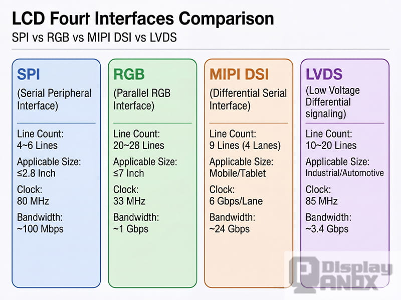
When engineers and product teams compare SPI, RGB, MIPI, and LVDS, they are really comparing four very different ways of moving image data from the host processor to the display. Each interface has its own strengths, limitations, and ideal application range. Some are perfect for compact embedded products. Others are built for smartphones, industrial systems, automotive displays, or larger HMI equipment.
This guide explains SPI, RGB, MIPI, and LVDS in a practical way, so it is easier to understand how they work, where they fit, and how to choose the right one for a real product.
1. Why display interfaces matter
A display interface is not just a connector or a group of signal lines. It defines how image data is transmitted, how often the screen must be refreshed, how complex the mainboard design becomes, and how much work the software team will need to do during bring-up.
The interface affects several critical factors at the same time:
-
data bandwidth
-
pin count and routing difficulty
-
EMI and signal integrity
-
refresh method
-
driver IC compatibility
-
development time
-
long-term supply flexibility
That is why interface selection should never be separated from panel resolution, frame rate, power budget, and processor capability.
2. What the display driver IC actually does
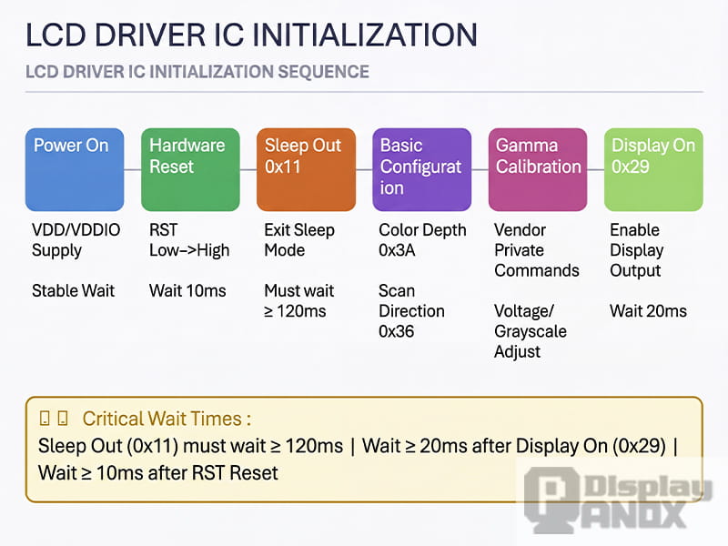
LCD driver IC initialisation process — Power-on → Reset → Sleep Out → Configuration → Display On
Before looking at SPI, RGB, MIPI, and LVDS one by one, it helps to understand the role of the display driver IC, often called the DDIC.
The DDIC sits between the host and the panel. It receives image data, controls scanning, applies the required voltages to pixels, and manages display timing. In many designs, the DDIC also determines whether the panel can store image data internally or whether the host must keep sending full frames continuously.
This difference is extremely important.
A display with internal GRAM can store the picture inside the driver IC. In that case, the host writes image data once, and the panel can keep refreshing from its own memory. This is one reason SPI works well for many small displays.
A display without GRAM does not hold the full image internally. The host must keep streaming frame data in real time. That is the typical behavior of many RGB panels and some high-bandwidth display systems.
In simple terms, the interface does not work alone. It works together with the DDIC architecture.
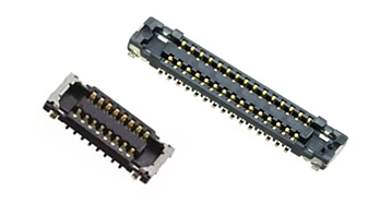
3. SPI interface: simple, low-cost, and ideal for small displays
SPI Interface Display Module
SPI is often the first display interface engineers learn, and for good reason. It is simple, widely supported, and easy to integrate into embedded systems.
A typical SPI display uses a small set of control and data lines, such as clock, data out, chip select, and data/command selection. This low pin count makes SPI attractive for MCUs, compact products, quick prototypes, and cost-sensitive designs.
SPI is best suited to small displays with relatively low resolution. In many practical projects, it is commonly used for panels around 2.8 inches or below, especially in devices such as handheld tools, smart home controls, wearables, simple HMI modules, and small consumer electronics.
The biggest advantage of SPI is design simplicity. Routing is easy, connector requirements are modest, and the software model is straightforward. If the panel includes GRAM, the host does not need to stream every frame continuously, which reduces system pressure.
The limitation is bandwidth. As resolution and refresh requirements increase, SPI quickly becomes less efficient. It can still drive a display, but animation smoothness, full-screen updates, and UI responsiveness may suffer if the data rate is not high enough.
SPI is a good choice when the product needs:
-
a small screen
-
low pin count
-
simple MCU integration
-
low development complexity
-
modest refresh requirements
If the product needs larger resolution, richer animation, or a more fluid UI, SPI is often no longer the right answer.
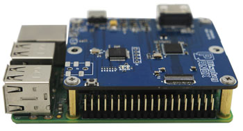
4. RGB interface: direct, fast, and common in medium-size embedded HMI designs
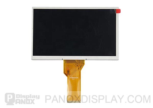
RGB Interface Display Module
RGB is very different from SPI. It is a parallel display interface that sends pixel data directly from the host to the panel. In a typical RGB interface, every pixel clock transfers pixel information, along with synchronization signals such as HSYNC, VSYNC, DE, and PCLK.
Because RGB is parallel, it can deliver much more data than SPI. That makes it a popular solution for medium-size and larger embedded displays, especially in industrial equipment, home appliances, medical interfaces, test devices, and HMI systems.
The strength of RGB is raw, direct pixel transfer. For applications that need a responsive graphical interface and higher resolution than SPI can handle comfortably, RGB remains a practical and cost-effective choice.
However, RGB also brings important trade-offs.
First, it uses many signal lines. Compared with SPI or MIPI, pin count is much higher. That increases connector size, PCB routing difficulty, and EMI risk. Second, many RGB panels do not include internal frame memory, so the host must continuously stream data. That means the processor or display controller must be able to sustain the required timing all the time.
This is why RGB is often paired with MCUs or MPUs that have dedicated LCD controllers or DMA support.
RGB is usually a strong fit when the product needs:
-
a medium-size display
-
straightforward real-time pixel output
-
moderate to high refresh performance
-
mature embedded controller support
-
lower protocol complexity than MIPI
RGB is often not the best fit when board space is tight, cable length is long, or the system needs a very low pin-count high-resolution interface.
5. Understanding RGB timing: HSYNC, VSYNC, HBP, HFP, VBP, and VFP
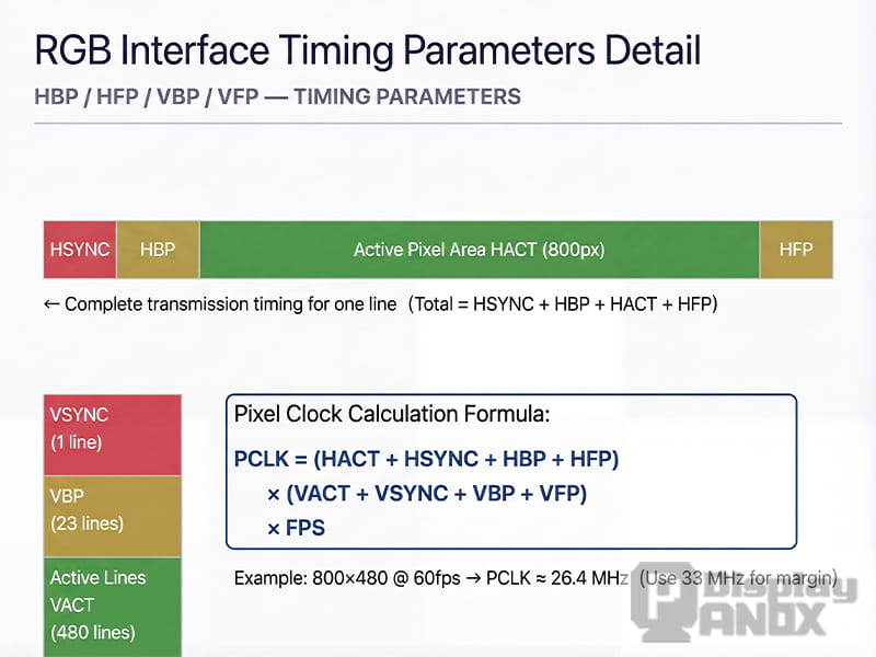
The Meaning of HBP, HFP, VBP and VFP Parameters, and the PCLK Calculation Formula
One reason RGB panels confuse beginners is timing.
A display frame is not made of active pixels alone. It also includes blanking intervals used for synchronization and internal processing. That is why panel timing tables include parameters beyond resolution.
The key timing terms are:
-
HSYNC: horizontal sync pulse width
-
HBP: horizontal back porch
-
HFP: horizontal front porch
-
VSYNC: vertical sync pulse width
-
VBP: vertical back porch
-
VFP: vertical front porch
These values define the total number of clock cycles and lines required to transmit a full frame, not just the visible image area.
In practical engineering, pixel clock is calculated from the total horizontal period, the total vertical period, and the frame rate. This means the required bandwidth is always higher than the active resolution alone suggests.
That is why two displays with the same visible resolution may still require different timing settings and different pixel clocks.
For RGB projects, stable timing configuration is often the difference between a display that works perfectly and one that shows flicker, shifted images, tearing, unstable colors, or no image at all.
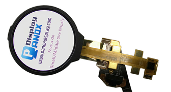
6. MIPI DSI: the mainstream choice for modern high-resolution compact displays
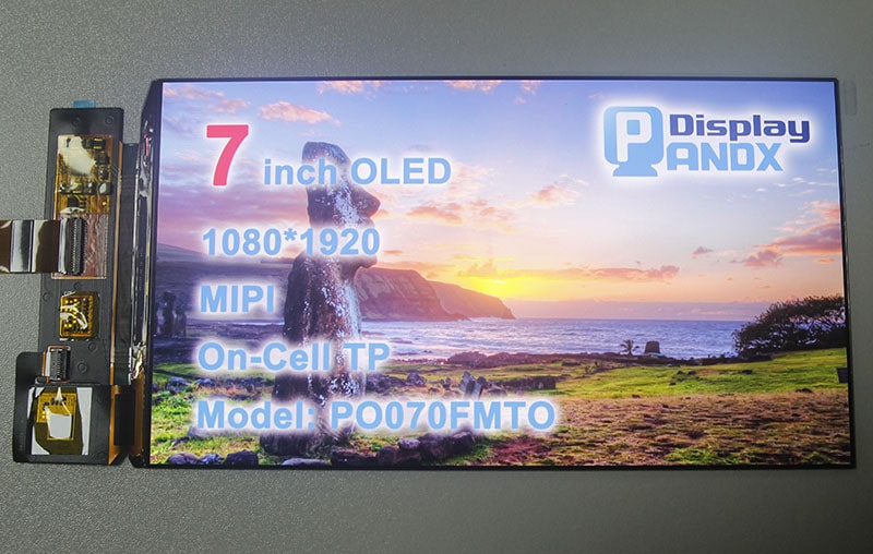
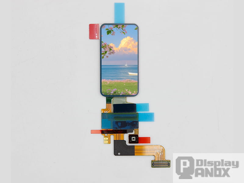
MIPI DSI Interface Display Module
MIPI DSI is one of the most important modern display interfaces, especially for smartphones, tablets, wearables, and advanced compact devices.
Compared with RGB, MIPI DSI dramatically reduces pin count while delivering much higher bandwidth. It uses high-speed differential lanes instead of wide parallel buses, which helps save board space and improves efficiency in compact electronics.
This is why MIPI DSI has become the standard language for many mobile-class displays.
Another major advantage of MIPI DSI is that it supports different operating approaches, including video-oriented transmission and command-oriented control, depending on the panel architecture and system design. This gives engineers more flexibility when balancing performance, power, and display behavior.
But MIPI DSI is not simply “better RGB.” It is also more complex.
Initialization is often highly panel-specific. Even when two displays have the same size and resolution, their initialization code may be different because the command sequence depends on the driver IC, panel tuning, power settings, gamma configuration, and vendor implementation. That is why MIPI bring-up is usually more sensitive than SPI or RGB bring-up.
MIPI DSI is usually the right choice when the product needs:
-
high resolution in a compact structure
-
low pin count
-
mobile-class display quality
-
advanced power and bandwidth efficiency
-
a modern processor platform with MIPI support
It is less attractive when the platform has no native MIPI output, development resources are limited, or the project requires very simple debugging and fast low-risk integration.
7. LVDS: reliable, mature, and still highly relevant for larger and industrial displays
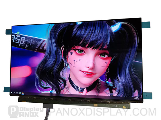
LVDS Interface Display Module
LVDS has been used for years in display systems, and it remains highly relevant in industrial, medical, automotive, and monitor-class products.
LVDS uses low-voltage differential signaling, which gives it strong noise immunity and good signal integrity compared with many single-ended interfaces. This makes it especially useful when signal quality, cable robustness, and system stability matter more than extreme protocol modernity.
For larger displays and longer internal cable runs, LVDS is often easier to manage than a wide RGB bus. It has long been a dependable choice in control terminals, industrial touch systems, diagnostic equipment, vehicle displays, and other applications where durability and predictable behavior are priorities.
LVDS is not the newest interface, but “old” does not mean obsolete. In many products, it is still the practical engineering choice because it is stable, well understood, and supported by a broad ecosystem of panels and controller solutions.
LVDS is often a good fit when the product needs:
-
reliable transmission in electrically noisy environments
-
support for larger displays
-
good signal integrity over longer board-to-panel distances
-
mature industrial and monitor-class integration
It may be less ideal when the target product demands the smallest possible connector, a highly mobile form factor, or the latest smartphone-style panel ecosystem.
8. SPI vs RGB vs MIPI vs LVDS: how to choose the right interface
There is no single best display interface. There is only the best interface for a specific product target.
If the design uses a small screen, a simple MCU, and a lightweight UI, SPI is often the most efficient choice.
If the product needs a medium-size embedded display with continuous refresh and the processor includes an LCD controller, RGB can be a very practical solution.
If the goal is a compact, high-resolution, modern product with strong visual performance, MIPI DSI is often the preferred path.
If the system uses a larger display in industrial, medical, or automotive conditions and values robust transmission and mature implementation, LVDS remains a strong option.
In real product development, the right decision should be based on six questions:
-
What resolution and frame rate does the display need?
-
Does the processor support SPI, RGB, MIPI, or LVDS natively?
-
Does the panel include internal GRAM or require continuous streaming?
-
How much PCB space and routing complexity can the hardware team accept?
-
How important are EMI control, cable length, and industrial reliability?
-
How much risk can the project tolerate during initialization and debugging?
The best interface choice is the one that fits both the display and the product architecture.
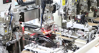
9. Why initialization and bring-up matter more than many teams expect
In display projects, interface selection is only half the story. Initialization is the other half.
A panel may have the right size, the right resolution, and the right interface, yet still fail in the prototype stage because the bring-up sequence is incomplete or incorrect. Sleep-out timing, pixel format, memory access control, gamma tuning, power settings, and optional features such as backlight control or tearing-effect handling can all affect whether the screen works correctly.
This is especially true for MIPI panels, but it also matters for SPI and RGB solutions.
In practice, display integration succeeds faster when teams have access to:
-
matched panel specifications
-
proven initialization code
-
timing recommendations
-
driver IC information
-
hardware design guidance
-
interface-level debugging support
That is why display selection should not focus on the panel alone. It should also include the integration path.
10. Final thoughts
SPI, RGB, MIPI, and LVDS are not interchangeable labels. They represent different design philosophies.
SPI prioritizes simplicity. RGB prioritizes direct pixel transfer. MIPI prioritizes bandwidth efficiency and compact integration. LVDS prioritizes robust differential transmission and long-term reliability.
Understanding these differences helps engineers avoid costly mistakes early in the design cycle. It also makes it easier to choose a display solution that fits the real product instead of forcing the product to adapt to the wrong interface.
For companies building embedded devices, industrial systems, smart control panels, automotive electronics, handheld terminals, or next-generation consumer products, choosing the right display interface is a core technical decision. When SPI, RGB, MIPI, and LVDS are evaluated together with driver IC behavior, timing requirements, and bring-up complexity, the final display solution becomes far more predictable, scalable, and commercially successful.