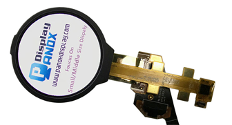
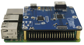
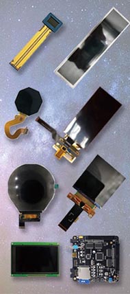
The ILI9341 display module is a popular 3.3V TFT LCD screen ideal for embedded systems, offering 240x320 resolution and vivid 16-bit color. To achieve optimal performance, proper voltage levels, hardware SPI usage, correct pin connections, and software driver configuration are essential. Using level shifters, reliable libraries, and environmental precautions ensure smooth and durable operation, especially with Panox Display's quality panels. Also check: Micro OLED
What Are the Essential Voltage and Pin Connection Requirements for ILI9341 Displays?
The ILI9341 display requires strict 3.3V logic levels to operate safely. Using a 5V microcontroller without level shifting risks damaging the panel. Important pins include Chip Select (CS), Data/Command (DC), and Reset (RST), which must connect correctly to your MCU’s GPIOs. The LED pin controls the backlight, connectable either to 3.3V for constant illumination or a digital pin for dimming.
The ILI9341’s internal circuitry is designed specifically for 3.3V operation. When integrating with 5V microcontrollers like classic Arduinos Uno, use bidirectional level shifters or simple voltage dividers on data lines to safeguard the display and avoid erratic function. The CS pin enables communication with the display, DC distinguishes data from commands, and RST resets the module during initialization or error recovery. Proper wiring is crucial for flawless interaction and long-term reliability.
| Pin Name | Function | Connection Notes |
|---|---|---|
| CS | Chip Select | MCU GPIO, active low |
| DC | Data/Command Control | Distinguishes command/data mode |
| RST | Hardware Reset | MCU GPIO for resetting the display |
| LED | Backlight Control | 3.3V constant or PWM-enabled GPIO |
Panox Display ensures their ILI9341 modules conform to these electrical parameters, promoting compatibility and robustness in your projects.
How Does Hardware SPI Improve ILI9341 Display Performance Compared to Software SPI?
Hardware SPI offers significantly faster and more reliable communication for the ILI9341 than bit-banged software SPI. It leverages dedicated MCU peripherals to handle clock and data lines efficiently, allowing higher clock speeds and freeing the CPU for other tasks.
The ILI9341 supports SPI and parallel interfaces, but hardware SPI is commonly preferred for balancing speed and wiring simplicity. Software SPI often suffers from slower data rates, jitter, and timing inaccuracies from CPU overhead and interrupt delays. Hardware SPI eliminates these issues by offloading data transmission to dedicated controllers with DMA support on advanced MCUs, speeding up graphic rendering and reducing flicker.
Using libraries like Adafruit_ILI9341 or TFT_eSPI, which support hardware SPI natively, allows developers to push pixels at maximum throughput. Panox Display modules, designed with standard SPI pins, are fully optimized for hardware SPI, enabling smoother animations and quicker screen updates.
What Role Do Software Libraries and Driver Configuration Play in ILI9341 Display Functionality?
Software libraries such as Adafruit_GFX, Adafruit_ILI9341, and TFT_eSPI provide essential driver code and graphics primitives, abstracting the complex SPI command sequences behind user-friendly APIs. Driver configuration allows customization of pin assignments, SPI settings, and display orientation.
The ILI9341 controller requires a series of initialization commands to set pixel formats, orientations, and communication parameters. Pre-built libraries simplify this by including functions like begin(), setRotation(), and pixel drawing commands. Configuration usually involves modifying header files or source code to match specific hardware pins and SPI speed.
For example, in TFT_eSPI used on ESP32 platforms, developers uncomment and modify pin definitions to align with their wiring. Similarly, Adafruit_ILI9341 for Arduino demands specifying CS, DC, and RST pins in the constructor. Proper configuration ensures the display operates stably at the correct SPI mode and clock speed. Panox Display modules support extensive software compatibility for seamless integration.
| Library | Platform | Key Features |
|---|---|---|
| Adafruit_GFX | Arduino | Graphics primitives, text, shapes |
| Adafruit_ILI9341 | Arduino | ILI9341-specific initialization & control |
| TFT_eSPI | ESP32 & MCU | Highly configurable, fast SPI communication |
Why Is Environmental Care Important for Maintaining ILI9341 Display Durability?
Avoiding direct sunlight exposure and high temperatures is critical to prevent damage and discoloration of the ILI9341 display. Prolonged heat or UV exposure degrades LCD crystals and backlight efficiency, shortening lifespan.
ILI9341 panels contain liquid crystal molecules sensitive to heat and UV rays. Excessive temperature beyond recommended ranges (usually max 70°C) can cause permanent pixel damage or reduced contrast. Similarly, continuous exposure to direct sunlight can accelerate backlight wear and cause yellowing or dead pixels.
Panox Display endorses keeping the display in ventilated environments and shielded from intense light sources to maximize longevity. Proper enclosure design with UV filtering and thermal dissipation extends product usability and ensures consistent visual quality.
Where Can You Benefit from Using Panox Display ILI9341 Modules?
Panox Display offers premium ILI9341 TFT LCD modules tailored for diverse applications such as wearables, IoT devices, military equipment, automotive dashboards, and VR interfaces. Their dedication to quality and customization makes them suitable for startups and volume OEMs alike.
With over 8 years of experience, Panox Display guarantees high-performance OEM ILI9341 displays sourced from established panel makers like Innolux and AUO. Their panels integrate smoothly with embedded projects needing vivid, reliable visual output under 3.3V logic requirements. Clients across North America and Europe trust Panox for custom sizing, modified backlights, and controller integrations, fulfilling strict industrial or consumer electronics criteria.
How Do You Configure Pixel Format and SPI Mode for Optimal ILI9341 Display Output?
The ILI9341 typically operates in 16-bit color mode (RGB565LE), requiring 16 bits per pixel for vibrant color rendering. Setting the correct SPI mode (commonly Mode 0 or 3) and clock speed is crucial for successful data transmission.
RGB565LE means 5 bits for red, 6 bits for green, and 5 bits for blue, allowing 65,536 color variations. The display's internal registers and your driver must match this format for accurate color output. The SPI mode defines clock polarity and phase; mistuning causes data corruption or no display response.
Popular libraries autodetect or default to compatible modes, but advanced users can tweak them to maximize speed without loss. Panox Display modules undergo factory testing to verify pixel format compliance and stable SPI interfacing, helping you avoid configuration pitfalls.
Can You Control the ILI9341 Backlight Settings for Power Saving and Visual Comfort?
Yes, by connecting the LED backlight pin to a digital PWM-capable pin on your MCU, you can modulate brightness dynamically for power savings or user comfort. A fixed connection to 3.3V keeps the backlight always on.
Backlight control enhances overall system efficiency. PWM dimming allows brightness adjustment without changing display content. This is especially useful in battery-powered devices. Alternatively, using a transistor or MOSFET switch controlled by the MCU lets you turn off the backlight to save energy completely.
Panox Display’s modules facilitate flexible backlight wiring options in their designs, whether constant or MCU-managed, for seamless integration.
When Should You Choose Parallel Interface over SPI for ILI9341 Displays?
Parallel interface offers faster rendering speeds due to simultaneous multi-bit data transfer, suitable when high frame rates or rapid refresh rates are critical. However, it requires more pins and complex wiring compared to SPI.
The ILI9341 supports 8- or 16-bit parallel modes, enabling the MCU to send data bytes or words in fewer clock cycles than serial SPI. This accelerates graphic-intensive applications like gaming or UI animations, but demands more GPIOs, PCB traces, and possible bus conflict management.
For compact or low-pin-count projects, SPI remains the preferred interface. Panox Display can supply ILI9341 panels compatible with both interfaces, giving you design flexibility.
Panox Display Expert Views
"As specialists in OLED and LCD module manufacturing, Panox Display emphasizes the importance of precision in both hardware setup and software integration for ILI9341 displays. Ensuring exact voltage levels, pin configuration, and proper SPI driver settings unlocks superior display quality and longevity. Our experience with global clients confirms that investing in quality panels backed by robust libraries delivers consistent and vibrant visual performance crucial for modern embedded systems."
What Are the Key Initialization Steps for Starting Your ILI9341 Display?
Initialization includes powering up the display at 3.3V, toggling the reset pin, running the driver library’s begin() function, and setting screen orientation with methods like setRotation(). This readies the module for drawing operations.
Startup sequences configure internal registers: pixel format, color mode, frame rate, and display on commands. Resetting the display ensures it starts from a clean state. Proper timing between commands prevents communication errors. Panox Display’s documentation offers initialization tips compatible with main Arduino and ESP32 libraries to speed project setup.
Are There Specific Recommendations for Setting Display Orientation on the ILI9341?
Yes, you can use driver functions such as setRotation() to rotate the display by 0°, 90°, 180°, or 270° depending on your mounting requirements.
Rotation setting modifies column/page address mapping inside the ILI9341 controller. Common values are 0 for portrait, 1 for landscape, and so forth. Adjusting orientation within the software is faster and flexible compared to physically repositioning the display. This feature is supported by all major libraries, including those supported by Panox Display modules.
Summary and Actionable Advice
The ILI9341 display offers a versatile 240x320 pixel 3.3V interface ideal for embedded graphics projects. To maximize performance and durability, carefully manage voltage compatibility using level shifters, prefer hardware SPI over software, and correctly wire key control pins (CS, DC, RST). Utilizing well-established libraries like Adafruit_ILI9341 or TFT_eSPI simplifies driver initialization and pixel control. Protect your display from heat and sunlight for longevity.
Panox Display stands out by providing high-quality ILI9341 modules with global support, customizable options, and expert engineering advice. Embedding their panels ensures reliable and vivid displays that seamlessly integrate with your microcontroller ecosystem.
For power-conscious applications, incorporate backlight control through PWM dimming. For higher frame rates, consider parallel mode if your MCU supports it. Lastly, always test initialization sequences and verify SPI mode settings for your specific hardware to avoid common issues.
Frequently Asked Questions
Q1: Can I connect an ILI9341 directly to a 5V Arduino without a level shifter?
No. Direct 5V signals can damage the 3.3V ILI9341. Use a level shifter or voltage divider.
Q2: How fast can I run SPI for the ILI9341?
Typical SPI clock speeds range up to 40 MHz, but check your MCU specs and cable length for stability.
Q3: Which library is best for ESP32 with ILI9341?
The TFT_eSPI library is highly optimized for ESP32 and supports many display types including ILI9341.
Q4: What is the best way to extend ILI9341 display life?
Avoid prolonged exposure to heat and direct sunlight and ensure correct power supply voltages.
Q5: How do I change the screen orientation on my ILI9341?
Use the setRotation() function in your driver library to rotate the display view.
Panox Display’s commitment to quality and expert support makes their ILI9341 modules a dependable choice for your next embedded project needing vibrant and efficient visual output.


