


According to Panox Display Research industry news, Scientific Reports recently published a major new study by Prof. Min Chul Suh’s team from the Department of Information Display at Kyung Hee University (Korea). The team developed a nano-textured light-modulation approach combining a Nanoporous Film (NPF) with a Refractive-Index-Matched Optically Clear Resin (OCR). This innovation successfully overcomes two long-standing challenges in top-emission microcavity OLEDs (TEOLEDs): the efficiency ceiling and angular color shift.
Measured results show that flexible TEOLED devices using this method achieved an external quantum efficiency (EQE) increase from 8.5% to 31.6%—a 370% improvement. Angular color shift (Δu′v′) dropped from 0.046 to 0.016, a 65.2% reduction. The devices also maintained stable performance under repeated bending and other mechanical stresses. This milestone opens a new development path for next-generation OLED products such as foldables, wearables, and large-area displays.
Related: Explore more flexible display models
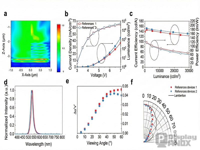
Figure 1 a. Three-dimensional FDTD scattered field simulation results for flexible OLEDs from the literature; b. Current density versus voltage versus luminance curve of the fabricated OLED device; c. Current efficiency versus luminance versus power efficiency curve of the fabricated OLED device; d. Normalised PL spectrum of the fabricated OLED device; e. Angular dispersion-related chromaticity coordinate shift of flexible OLEDs from the literature; f. Lambertsian luminance characteristic curve of flexible OLEDs from the literature.
1. Industry Dilemma: The Double Shackles of “Efficiency and Viewing Angle” in High-End OLED
Amid rapid display-technology iterations, active-matrix organic light-emitting diode (AMOLED) displays—thanks to their ultra-thin form factor, high contrast, millisecond-level response, and excellent mechanical flexibility—have become the core display solution for smartphones, smartwatches, foldable devices, and more.
Among them, top-emission AMOLED (TEOLED) redirects emission away from the substrate, avoiding constraints from backplane wiring and enabling a higher aperture ratio. This gives it irreplaceable advantages in high-end applications such as 4K/8K ultra-high-definition displays and compact wearable devices, and it is widely regarded as a key direction for next-generation display development.
However, TEOLED’s microcavity structure carries inherent critical drawbacks. The Fabry–Pérot microcavity formed between a reflective bottom electrode and a semi-transparent top electrode can selectively enhance specific wavelengths through resonance, improving color purity and narrowing the emission spectrum. Yet it also introduces strong angle dependence. As viewing angle changes, the optical path length shifts, causing pronounced spectral drift—especially a blue shift at oblique angles—which severely impacts multi-user viewing scenarios and large-format visual experience. This issue becomes even more prominent in emerging form factors such as foldable, rollable, and stretchable displays, making it a key bottleneck for the industry.
Meanwhile, traditional light-extraction techniques struggle to balance efficiency and stability. Nanoporous films (NPF) are a promising candidate: by scattering waveguided modes and coupling out trapped light, they can promote Lambertian emission and mitigate angular color shift. But conventional NPF fabrication has clear limitations. NPF made via mist-assisted spin coating often contains irregular concave hemispherical voids on the surface, leading to substantial diffuse backscattering and optical loss. More critically, when NPF is applied to bottom-emission OLEDs (BEOLEDs), it can degrade under moisture and oxygen. In addition, the refractive-index mismatch between air-filled nanopores and the glass substrate can offset light-extraction gains, greatly reducing real-world effectiveness.
The industry urgently needs an integrated solution that can simultaneously break the efficiency barrier, solve angular color shift, and remain compatible with flexible form factors. Prof. Suh’s team directly targets this pain point, achieving a leap in OLED performance through deep integration of materials innovation and structural design.
Learn more: What is 'Organic' LED - How OLED Works
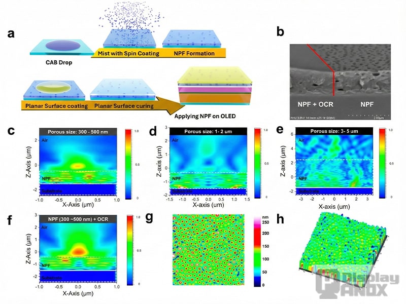 Figure 2 a. Preparation process of NPF-based TEOLED; b. SEM image of NPF surface morphology in the OCR layer; c. SEM image of NPF surface morphology in the OCR layer; d–f. Three-dimensional FDTD simulation diagrams of cross-sectional electric field scattering patterns for NPFs with different pore sizes and composite films; g–h. Ionic conductivity microscopy analysis of NPF.
2. Technological Innovation: A Synergistic Breakthrough via Nano-Texturing and Refractive-Index Matching
To address the inherent challenges of TEOLEDs, the team proposed a structural, engineered optical-design strategy. The core idea is to combine NPF with a refractive-index-matched OCR, optimizing the device stack to create an “NPF + OCR” synergistic system that simultaneously improves light-extraction efficiency and angular stability.
(1) Structural Redesign: An Inverted Lamination Architecture to Overcome Traditional Limitations
Instead of depositing NPF directly onto the OLED active layers, the team adopted an inverted lamination design: NPF is fabricated on the inner surface of the encapsulation glass, then a UV-curable refractive-index-matched OCR (n = 1.56) is spin-coated to fill the concave voids on the NPF surface. This delivers two key advantages:
-
OCR smooths the NPF surface, reducing optical loss from interfacial scattering.
-
The nanoporous structure remains intact, continuing to redistribute light angularly.
More importantly, the TEOLED structure provides NPF with a natural environmental shield, preventing moisture and oxygen from degrading the material. At the same time, refractive-index matching among OCR, NPF, and the encapsulation glass minimizes reflection loss, allowing the scattering effect of NPF to be fully utilized. Comparative experiments show that conventional NPF, with a surface refractive index close to air (n ≈ 1), suffers significant mismatch against encapsulation glass (n ≈ 1.5), causing over 25% efficiency loss—a problem the new OCR-filled design resolves.

Figure 3 a. Optical microscopy morphology characterisation of NPF with and without OCR filling; b. Schematic diagram of NPF TEOLED structure and optical extraction path; c. Three-dimensional FDTD simulation of electric field scattering patterns in cross-sections of NPF TEOLED devices with and without OCR layer; d. Comparison of total power flux magnitude across all simulated devices.
(2) Materials Optimization: Precisely Tuned Nanoporous Film Fabrication
The team produced high-performance NPF via mist-assisted spin coating. A chloroform solution of cellulose acetate butyrate (CAB) forms a porous matrix; water vapor is precisely introduced during spinning so that, after curing, a uniform nanoscale pore network forms in the polymer film.
To maximize light extraction, key parameters were optimized: polymer concentration was set to 8 wt%, spin speed to 2000 rpm, yielding an NPF thickness of about 1 μm with uniformly distributed nanopores.
Both 3D finite-difference time-domain (FDTD) simulations and experiments confirm that pore size decisively affects scattering efficiency. NPF with 300–500 nm pores shows the strongest omnidirectional scattering intensity, whereas larger-pore NPF (1–2 μm and 3–5 μm) exhibits much weaker scattering—validating the technical advantage of smaller pore structures. Laser interferometric confocal microscopy (LICM) further shows that the porous surface structure provides an ideal physical basis for scattering, with optimized depth and spatial uniformity.
(3) Performance Enhancement: OCR’s Multiple Critical Roles
OCR plays several crucial roles beyond filling surface voids and smoothing the morphology. It also eliminates air gaps between the encapsulation glass and the OLED, preventing total internal reflection and associated light trapping. Experimentally, after OCR filling:
-
Total transmittance (T.T) increases from 82.1% to 94.9%
-
Parallel transmittance (P.T) rises from 32.9% to 70.7%
-
Haze decreases from 59.8% to 25.5%
This achieves a strong balance between transparency and controlled scattering.
In addition, OCR’s UV-curable nature improves assembly efficiency and is compatible with flexible substrates. The team used a modular concept: the NPF scattering substrate can be mass-produced independently, then laminated onto the OLED stack—improving yield and avoiding damage to organic layers from direct deposition. This provides a practical route to volume manufacturing for flexible displays.
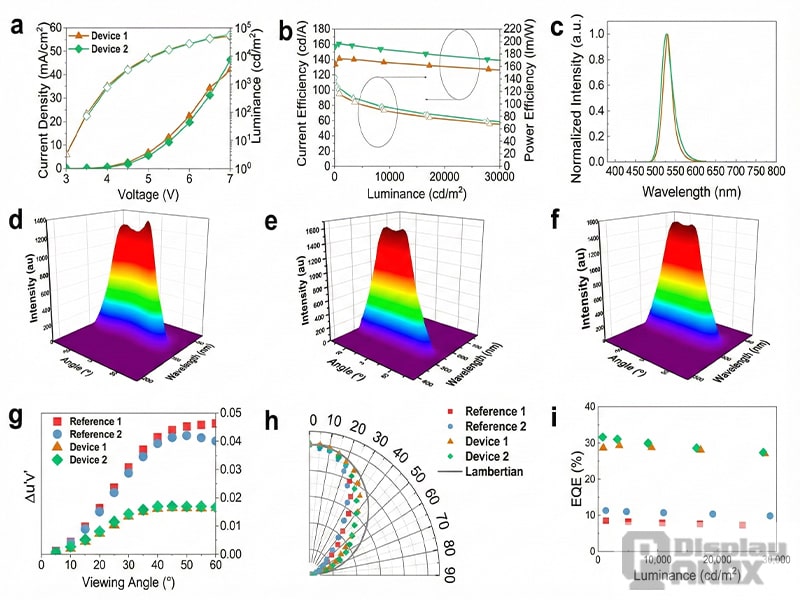
Figure 4: Structural design and EL performance curves of reference OLED devices: a–c. Current density–voltage–luminance curves, current efficiency–luminance–power efficiency curves, and normalised EL spectra; d–f. Angle-dependent EL spectral contour plots for three reference OLED devices; g. Comparison of angular dispersion characteristics between the proposed scheme and reference OLED devices; h. Comparison of Lambertian emission characteristics between the proposed scheme and reference OLED devices; i. Comparison of EQE for all OLED devices after light coupling factor correction.
(4) Flexibility Compatibility: Stable Mechanical and Optical Performance
To meet wearable requirements, the team adapted the approach for flexible devices. Results confirm excellent compatibility with flexible substrates, maintaining stable optical and mechanical behavior under bending. Finite element analysis (FEA) indicates the flexible device can withstand a critical stress up to 8000 MPa, retaining structural integrity across 0%–100% bending. In repeated bending tests, no cracks or notable performance degradation were observed, meeting wearable-use demands.
Learn more: OLED Wearable Device
3. Performance Leap: Triple Breakthrough in Efficiency, Color Stability, and Flexibility
Through systematic experimental validation and simulation, TEOLED devices using the “NPF + OCR” approach achieved step-change improvements across key performance metrics, substantially outperforming conventional reference devices.
(1) Optoelectronic Efficiency: Setting a New Benchmark
In electroluminescence (EL) testing, Device 2 showed particularly strong performance. At a driving voltage of 6 V, current density reached 23.1 mA/cm², significantly higher than 19.3 mA/cm² for the reference device. Current efficiency (CE) reached 161.1 cd/A, and power efficiency (PE) reached 141.7 lm/W, improving by 9.9% (from 146.6 cd/A) and 13.3% (from 125.1 lm/W), respectively. After correction using the Lambertian correction factor (LCF), EQE jumped from 8.5% to 31.6%—a 370% increase, setting an efficiency record for similar devices.
Spectral measurements show Device 2 has a peak wavelength of 527 nm and a full width at half maximum (FWHM) of 30 nm. It preserves the high color purity of a microcavity structure, while NPF scattering prevents overly narrow spectra from worsening angular dependence. By comparison, the reference device peaks at 535 nm with FWHM 30 nm, but suffers severe angular color shift, limiting practical usability.
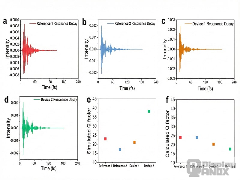
Figure 5 a–d. Three-dimensional FDTD simulation plots of the resonant attenuation characteristics for all fabricated TEOLEDs; e–f. Comparison plots of the quality factors for all fabricated TEOLED devices.
(2) Angular Stability: Consistent Color Across a Wide Viewing Range
Angular dependence is a core advantage of this approach. Conventional TEOLEDs can show up to a 22 nm blue shift in peak wavelength from −60° to 60°; even with OCR alone, a 19 nm blue shift remains. With the NPF + OCR method, Device 2 reduces the peak-wavelength blue shift to just 10 nm over the same range, and lowers angular color shift (Δu′v′) to 0.016, a 65.2% reduction versus the reference—achieving near-ideal color consistency across viewing angles.
Crucially, the emission distribution approaches an ideal Lambertian profile, maintaining uniform brightness and color over wide angles. 3D FDTD simulations show NPF scattering produces a more uniform optical field in the x–z plane, while OCR’s refractive-index matching further boosts outcoupling efficiency, forming an omnidirectional emission pattern. This directly addresses long-standing off-axis visibility problems in flexible and large-area displays.
(3) Mechanical Reliability: A Strong Foundation for Flexible Applications
To validate flexible potential, the team fabricated a flexible version (Device 3) and performed comprehensive mechanical tests. At 7 V, brightness remains almost unchanged even at 100% bending. After 400 bending cycles, only slight luminance degradation appears, demonstrating excellent flexibility and durability.
In demonstrations, the flexible device can conform to human skin or wrap around curved objects such as chopsticks while maintaining stable emission—satisfying wearable needs for smartwatches and AR glasses. Angular testing further confirms that color stability in the flexible state matches that of rigid devices, providing critical support for commercialization.
(4) Cost Advantage: Enabling Large-Scale Production
This technology offers a significant cost benefit. The estimated raw-material cost to produce 25 cm² of NPF is under US$0.1, using common chemicals such as CAB and chloroform—without expensive specialty materials or complex lithography. In contrast, conventional light-extraction methods (e.g., microlens arrays, photonic crystals) rely on high-precision lithography and specialized materials, making them costly and difficult to scale.
Moreover, the modular manufacturing approach—independent NPF substrate production followed by lamination integration—fits existing OLED production lines without major equipment changes, further lowering industrialization barriers. The “high performance + low cost” combination lays a strong foundation for rapid commercialization.
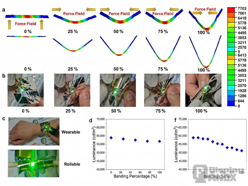
Figure 6 a. FEA simulation diagram of reference OLED device 3 under 0%–100% bending strain; b. Photograph of reference OLED device 3 under 0%–100% bending strain; c. Demonstration of reference OLED device 3 conforming to the human hand and flexibility when wrapped around chopsticks; d–f. Curve diagrams showing the relationship between brightness and bending strain percentage, and brightness versus bending cycle count for reference OLED device 3.
4. Research Outcomes: From Laboratory Validation to Industrialization
Through rigorous theoretical analysis and experimental validation, this study reveals the optical modulation mechanism created by synergy between nano-textured structures and refractive-index matching. Q-factor analysis indicates that NPF scattering reduces optical coherence within the microcavity, moderately broadening the emission spectrum and suppressing angular color shift; meanwhile, OCR’s index matching strengthens optical resonance, improving device efficiency. This precise control of light–matter interaction provides new theoretical guidance for optical design in organic optoelectronics.
The strong agreement between 3D FDTD simulations and experimental results further validates the scientific robustness and reliability of the approach. Simulations not only predict optical-field distributions, power-flow changes, and angular dependence, but also offer critical guidance for structural parameter optimization—demonstrating the value of combining theory and experiment.
Application potential extends beyond consumer electronics to automotive displays, medical displays, and outdoor large-format screens. In automotive use, wide-angle color stability supports both driver and passenger viewing; in medical displays, high resolution and accurate color help enable precise diagnosis; in outdoor large screens, high brightness and angular stability improve multi-viewer experience.
The team notes that the method has been verified in green TEOLEDs, and next steps include extending to red and blue devices, as well as exploring applications in emerging technologies such as quantum-dot OLEDs and perovskite OLEDs. With continued optimization of materials systems and further structural refinement, even higher efficiency and better stability are expected—opening new space for the display industry.
Related: What Do You Need To Do Before Customizing A Touch?